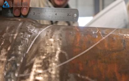
Surface Corrosion and Scratches on Steel
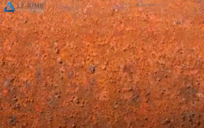
(1) Causes
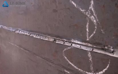
① Improper storage after rolling: exposure to moisture, outdoor storage, subjection to sun and rain, or an environment with highly corrosive air, leading to oxidation and subsequent corrosion.
② Surface damage occurring during fabrication, installation, or straightening processes.
(2) Preventive Measures
① Implement rigorous inspection of raw materials before they enter storage.
② Defects within acceptable limits may be repaired (e.g., by grinding); materials with defects exceeding these limits must be rejected.
③ Prioritize proper material storage: ensure steel is protected from moisture, sun, and rain. For steel stored outdoors for extended periods, apply anti-corrosion surface treatments.
④ Ensure the correct use of tools and equipment during fabrication and installation. Scratches or marks caused by lifting/handling equipment should be repaired by weld-filling followed by grinding.
Presence of Burrs, Jagged Edges, Missing Corners, or Serrations After Cutting
(1) Causes
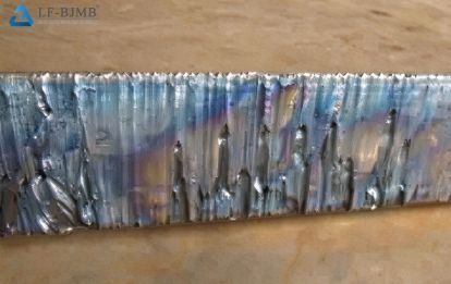
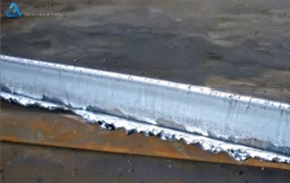
① Improper cutting speed, incorrect torch/nozzle angle, unsuitable nozzle selection, or incorrect oxygen pressure.
② Failure to promptly clean up the cut edges.
③ Severe surface corrosion on the steel plate without prior treatment.
(2) Preventive Measures
① Adjust equipment and process parameters in strict accordance with technical specifications.
② Select the appropriate cutting nozzle and accurately adjust the torch/nozzle angle before cutting.
③ Adjust the flame intensity based on the thickness of the steel plate.
④ Promptly remove iron oxide and other debris after cutting.
⑤ Ensure the work platform remains level.
⑥ Repair any quality defects immediately through weld-filling and grinding.
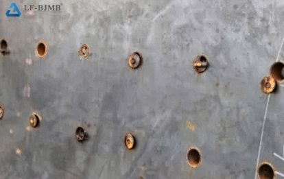
Incorrect Hole Positioning, Accumulation of Metal Shavings/Burrs, and Poor Hole Quality
(1) Causes
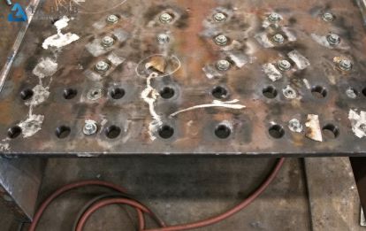
① Failure to use a center punch, or incorrect placement of the center punch mark.
② Misalignment with reference lines when drilling through stacked steel plates.
③ Excessive thickness of stacked plates, failure to clamp them securely, or an uneven work platform/surface.
④ Insufficient magnetic force in magnetic-base drills.
⑤ The drill bit is not sharpened correctly; the point angle, clearance angle, and chisel edge angle do not meet the specified requirements.
(2) Preventive and Corrective Measures
① Ensure thorough preparation before production begins: sharpen drill bits properly, familiarize yourself with the technical processes and acceptance standards, conduct self-inspections as required, and promptly correct any issues identified.
② Maintain accurate reference lines when drilling through stacked steel plates.
③ Use a drill jig (template) when drilling multiple identical parts.
④ When drilling through multi-layered plates, implement effective measures to prevent the layers from shifting.
⑤ Ensure drill bits are properly sharpened and apply sufficient coolant during the drilling process.
⑥ Promptly remove burrs, metal shavings, and debris after drilling.
⑦ If hole deviation occurs—most commonly during lateral (side) drilling—use a magnetic-base drill, a drill jig, or first create a 4mm pilot hole with a handheld electric drill before enlarging it with a magnetic-base drill.
⑧ Where permitted by the design, use a manual reamer to correct issues such as poor surface roughness, incorrect hole diameter, ovality, inaccurate hole spacing, or deviations in the perpendicularity of the hole centerline. If the design does not permit this, the hole must be repaired via welding (in accordance with welding procedure specifications), ground flush, and subjected to non-destructive testing (NDT). Once cleared, the hole should be re-marked and re-drilled, or drilled using a jig. It is strictly prohibited to simply plug a hole with foreign material and weld over the surface.
Excessive Dimensional Deviation in Components
(1) Causes
① Lack of familiarity with technical processes during layout or marking (lofting), leading to the use of incorrect templates (or rods) or the misreading of dimension lines.
② Errors in technical requirements, or unclear technical briefings or documentation.
③ Use of uncalibrated measuring tools, resulting in significant reading errors; incorrect adjustment of measuring instruments; or applying improper force (too much or too little) when using measuring tools for long distances.
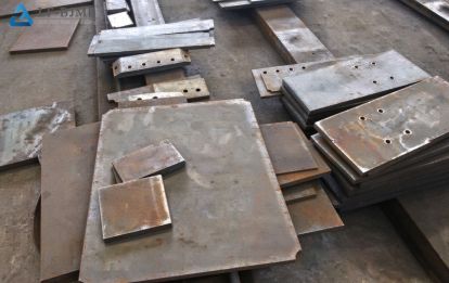
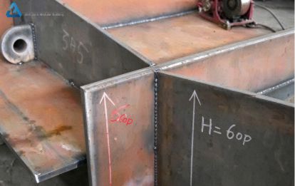
(2) Preventive and Corrective Measures
① Conduct a technical briefing before work begins to clarify all processing requirements.
② When preparing technical documentation, account for all relevant factors, including the relationships between components, specific processing requirements, and adjustments for plate thickness.
③ Ensure diligent work practices by strengthening the review of technical documentation and enhancing both self-inspections and peer inspections throughout the fabrication process. ④ Measuring tools must be calibrated and qualified; measured values should be adjusted correctly. For long-distance measurements, a spring scale should be used.
Butt welds not staggered
(1) Causes
① The fabrication layout failed to ensure that butt joints in flanges and webs are staggered by at least 200 mm.
② Incorrect orientation or positioning of plates during shop splicing.
(2) Preventive Measures
① Ensure the fabrication layout complies with relevant standards.
② Perform assembly in strict accordance with design requirements and process specifications.
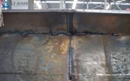
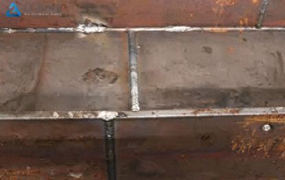
Assembly areas not ground; excessive assembly gaps
(1) Causes
① Personnel failed to clean the assembly areas prior to assembly, as required by the process specifications.
② Imprecise assembly operations—such as errors in marking or cutting, or failure to pre-straighten components.
③ Component dimensions fall outside specified tolerances.
(2) Preventive Measures
① Before marking, remove rust, burrs, and oil/grease from T-joint areas (where flanges meet webs) and from a 30–50 mm wide strip on both sides of the web.
② Strengthen process briefing/training and enhance supervision throughout the workflow.
③ Ensure precision during marking, cutting, and assembly.
④ Verify component dimensions prior to assembly.
⑤ Do not insert foreign objects—such as welding wire or electrode stubs—into assembly gaps.
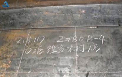
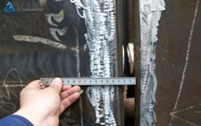
Significant misalignment (offset) at joints; improper assembly sequence
(1) Causes
① Cross-sectional dimensions at the butt joint exceed tolerances.
② Assembly performed before butt welds were completed.
③ Failure to follow the prescribed assembly sequence.
(2) Preventive Measures
① Straighten circular pipes before assembly; ensure diameter and roundness deviations meet specification requirements.
② Carefully adjust the alignment at butt joints to ensure any offset remains within standard limits.
③ Complete all butt welds before proceeding with further assembly.
④ Strictly adhere to the specified assembly sequence.
Misalignment (displacement) of embedded steel components
(1) Causes
① Inadequate securing or bracing of embedded components during installation.
② Errors in calculating the center position of embedded components.
③ During concrete pouring, vibration is performed too close to or directly against the embedded components.
④ When checking the positions of embedded components, an uneven slab surface leads to errors in the inspection results.
⑤ External forces applied during concrete pouring cause the embedded components to shift.
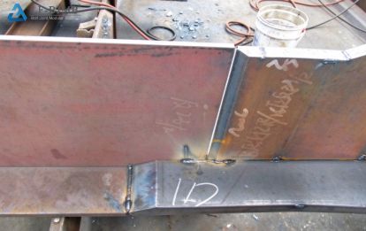
(2) Preventive and Remedial Measures
① Clearly describe reinforcement measures for the installation of embedded components during the technical briefing, and ensure that workers fully understand and master them.
② Include specific precautions for concrete vibration around embedded components in the concrete pouring technical briefing, and ensure that workers are aware of them.
③ Verify the calculated center positions of embedded components before proceeding with on-site layout (marking).
④ Ensure that embedded bolts, steel plates, and similar items are securely fixed; implement additional structural measures—such as installing bolt frames or steel reinforcement supports—if necessary.
⑤ Use double-sided tape or other materials to fill the gaps between the embedded components and the formwork, preventing concrete slurry from seeping onto the surfaces of the components and causing them to become recessed.
⑥ Prevent accidental impact to embedded components during the pouring process. Assign personnel to monitor and inspect the positions of these components continuously, and address any issues immediately. Do not proceed with subsequent construction steps involving these embedded components until the concrete has reached the specified strength.
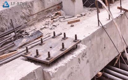
Anchor Bolt Misalignment (Preventing Nuts from Being Tightened)
(1) Causes
① Errors in positioning or layout (marking).
② Failure to monitor and re-verify the positions of embedded bolts after installation.
③ Interference (collision) between the embedded bolts and the foundation reinforcement, which affects their positioning.
④ Lack of protection for bolt threads prior to concrete pouring, leading to contamination or damage that prevents nuts from being tightened.
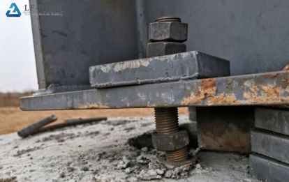
(2) Preventive and Remedial Measures
① Strictly re-verify survey coordinate points to ensure that any errors in the coordinate system remain within permissible limits and that positioning is accurate.
② Cross-reference the civil engineering foundation drawings to clarify the spatial relationship between the steel structure’s embedded components and the foundation itself; resolve any conflicts and establish a logical sequence for the installation of the steel structure’s embedded components.
③ Conduct timely re-verification and adjustments throughout the foundation construction process—specifically, perform continuous monitoring and measurements during the concrete pouring phase. ④ Once the anchor bolts are embedded, implement protective measures for the finished components immediately (apply anti-rust grease to the threaded ends and wrap them completely with tape; additionally, place warning signs on-site to prevent damage or collisions resulting from concurrent work activities).