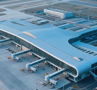
Long-span hangars require large, column-free interior spaces to accommodate aircraft parking and maintenance operations; the roof structure serves as the technical core of the entire hangar project.
Cylindrical reticulated shells (curved grid shells), flat trusses, and hollowed-out (open-web) grid structures are the three most commonly used roof types today. Each offers distinct advantages and disadvantages regarding structural behavior, design challenges, construction methods, and life-cycle costs.
By examining common issues faced by long-span hangars—such as thermal stress, wind and snow loads, stability control, on-site installation, and long-term operation and maintenance—this comparison of the three structural options provides a useful reference for the initial selection phase of hangar projects.
This article is divided into three sections. The first section covers:
1. Cylindrical Reticulated Shells (Curved Grid Shells)
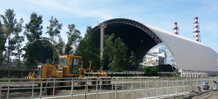
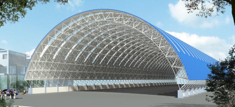
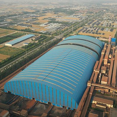
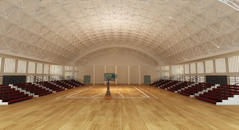
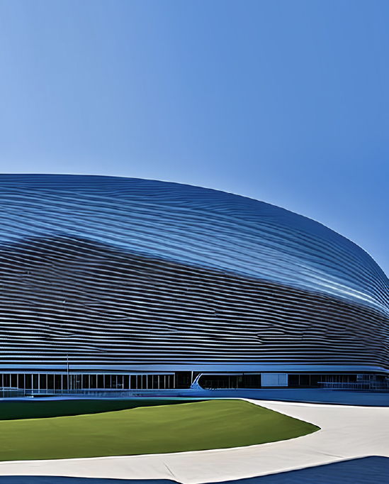
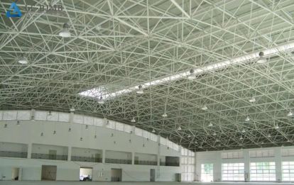
Cylindrical reticulated shells are spatial structures that use curved grid geometry to achieve long spans. Their curved forms can create an efficient load-bearing system. These structures may suit hangars with spans of 60 meters or more, depending on the design requirements.
The shell effect can help distribute loads efficiently and reduce steel consumption. However, engineers must address several challenges during design, fabrication, and construction.
1.1 Structural Behavior and Design Challenges
Cylindrical reticulated shells rely on membrane forces and bending moments to resist applied loads. Vertical loads, uneven snow accumulation, and wind pressure can produce complex internal force distributions.
Engineers must therefore carry out detailed structural analysis. They should also assess both global and local buckling. Thin-shell structures can be sensitive to initial imperfections, including member curvature and deviations introduced during fabrication or installation.
These imperfections may significantly reduce the critical buckling load. Accurate modeling and careful control of fabrication tolerances are therefore essential.
1.2 Thermal Effects and Supporting Structures
Long-span metal shells also require careful thermal analysis. Large temperature fluctuations can cause expansion, contraction, and additional thermal stress.
The interaction between the shell and its supporting structure is another important consideration. Engineers must assess how support stiffness, boundary conditions, and temperature changes affect structural behavior.
Seismic performance also requires project-specific evaluation. Depending on the site conditions, structural configuration, and applicable design codes, engineers may need to conduct detailed dynamic analysis, including time-history analysis where appropriate.
1.3 Materials and Connection Design
Cylindrical reticulated shells feature three-dimensional curved grids. Their geometry often requires many joints with different connection angles.
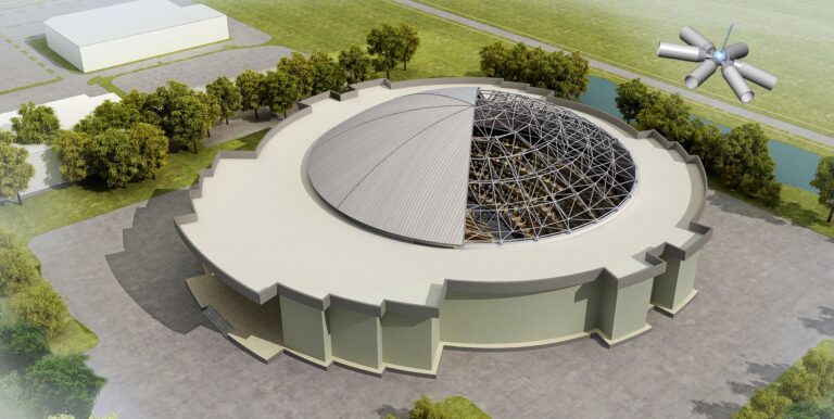
Bolted-ball connections must accommodate spatial members that meet in different planes. Welded-ball connections, by contrast, may require substantial welding work, particularly when the construction process involves site welding.
Long-span members may also require high-strength steel. This increases the importance of appropriate welding procedures, material selection, and resistance to brittle fracture.
Engineers and fabricators must develop accurate three-dimensional geometry for all members and joints. They should also conduct sectional or full-scale pre-assembly when necessary. These checks help verify fabrication dimensions before the team proceeds with full installation.
Although these measures improve dimensional control, they also increase the demands on technical coordination and project management.
1.4 Construction and Installation Challenges
Construction and installation can present major challenges for cylindrical reticulated shells.
Traditional full-scale scaffolding may require large quantities of temporary steelwork. In some cases, the temporary structure can approach the steel quantity of the permanent structure. This can increase costs and extend the construction schedule.
For long-span shells, engineers may consider alternative methods. These include incremental sliding of structural sections and integrated hydraulic lifting.
However, irregular geometry and heavy structural components require careful planning. The installation team must control the structure’s orientation and internal forces throughout each construction stage.
1.5 Installation Accuracy and Quality Control
Installation errors can affect the final geometry and redistribute internal forces. As a result, the team must control fabrication tolerances, lifting positions, and closure procedures carefully.
Achieving accurate closure at multiple elevated connection points can be particularly difficult. Engineers should establish clear dimensional tolerances and a reliable measurement process before installation begins.
Welded-ball connections also require strict quality control when workers perform welding at height. The team must manage welding quality and assess residual stresses where necessary.
A well-planned installation sequence helps reduce these risks. It also improves coordination between the design, fabrication, and construction teams.
1.6 Operation and Maintenance
Curved roof surfaces can make inspection and maintenance more difficult than on conventional flat roofs. Workers may face additional challenges when inspecting connections, cleaning gutters, and accessing drainage components.
Longitudinal drainage also requires careful planning. Engineers must define suitable drainage paths and prevent water from accumulating in low points.
In addition, the maintenance strategy should provide safe access to critical structural components. Regular inspections can help identify coating deterioration, connection issues, and drainage problems before they become more serious.
1.7 Recommended Measures to Address These Challenges
The following measures can help improve the design, construction, and long-term performance of cylindrical reticulated shells.
During the design phase
Engineers should analyze geometric and material nonlinearity where the structural behavior requires it. They should also account for initial imperfections using an appropriate imperfection-based analysis method, such as a consistent imperfection mode approach where applicable.
BIM-based parametric modeling can connect structural analysis, joint design, fabrication detailing, and construction simulation. This approach helps maintain consistent geometry and improves information exchange between project teams.
For wind-load assessment
Wind tunnel testing or computational fluid dynamics (CFD) simulations can help determine wind pressure distributions on complex curved roofs. Engineers should select the appropriate method according to the roof geometry, aerodynamic complexity, and applicable design requirements.
For connection reliability
The design team should select connection details according to the calculated forces, material properties, fabrication capabilities, and applicable standards. Potential solutions include 10.9S high-strength bolts, reinforced conical connectors, hollow welded balls, and cast-steel joints.
These options are not interchangeable in every application. Engineers must verify their suitability for the specific connection and loading conditions.
During construction and installation
Three-dimensional laser scanning can help the team compare the installed structure with the digital model. Sliding and integrated lifting methods may also reduce the need for extensive full-scale scaffolding, depending on the project conditions.
Construction simulation can help identify potential conflicts before installation begins. In addition, RFID technology can track members and joints throughout fabrication, transportation, and installation when the project adopts a suitable tracking system.
Together, these measures can strengthen coordination among design, detailing, fabrication, and installation teams. They also help improve dimensional control and construction management for complex long-span roofs.