


 About Us
 2025-07-11
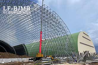
Space frame structures are a type of building structure composed of supports, members, spherical nodes, and enclosure systems. They are classified by construction materials into steel space frames, aluminium space frames, wooden space frames, plastic space frames, reinforced concrete space frames, and composite space frames, among others. However, steel space frames are currently the most widely used. They have developed the fastest and are the most widely applied in spatial grid structures. Space frame structures are either formed as a single continuous spatial body or expanded from multiple members. Each component is an integral part of the overall structure, distributing loads according to spatial geometric characteristics. Internal force transmission is straightforward, and the structural integrity is excellent. This allows for large spans to be achieved with smaller cross-sections, reducing structural self-weight and enhancing overall economic efficiency. Space frame structures come in various forms, capable of presenting diverse architectural floor plans. They feature lightweight and aesthetically pleasing designs with a strong sense of spatial openness, while also meeting large span requirements with minimal steel usage. They are commonly used as roof structures for buildings such as sports arenas, theatres, exhibition halls, waiting halls, stadium grandstand canopies, aircraft hangars, and large-span workshops with wide column spacing. Their advantages include low spatial stress, light weight, high rigidity, and excellent seismic performance; their disadvantages include a large number of members converging at nodes, making fabrication and installation relatively complex.
Space truss structures are a type of spatial rod system structure, where load-bearing rods are connected through nodes according to a specific pattern. Nodes are typically designed as hinged joints, with rods primarilying transmitting axial forces, resulting in relatively smaller cross-sectional dimensions. These spatially intersecting members mutually support one another, integrating the load-bearing members with the support system in an organic manner, resulting in economical material usage. Due to the regularity of the structural assembly, a large number of members and nodes have identical shapes and dimensions, facilitating factory production and on-site installation. Below, we will discuss the design considerations for the nodes and enclosure systems of steel space frame structures.
I.Support Node Design Space frames are typically supported on lower structural elements such as column tops or beam tops. Support nodes refer to the nodes where the space frame is connected to the supporting structure. The detailed design of a space frame begins with the support nodes, as their elevation and position determine whether the space frame can be constructed normally.
The elevation of the top surface of the lower concrete or steel structure and the position of embedded components must be accurate.
The form of the support node must be determined. Common types include pot-type supports and rubber plate supports. Attention should be paid to the direction of support constraints.
Edge support nodes are often located near parapets. The clear distance between the support node and the parapet should generally be maintained at over 50 mm.
Intermediate supports bear heavy loads and often have larger base plate dimensions. Attention should be paid to whether the cross-section of the lower concrete columns or steel columns meets the requirements. If not, an enlarged column head node should be adopted.
For upper chord-supported space frames, verify that the support position members do not collide with the lower support structure. The distance from the bottom of the support ball node to the support base plate must meet the requirement that diagonal braces do not collide with columns or beams. 6. Limiting measures must be taken on the outer side of the space frame supports.
II.Spherical Node Design
Spherical nodes in space frames are divided into welded spheres and bolted spheres. Bolted spheres are connected using high-strength bolts, while welded spheres are connected using on-site welded joints.
Design requirements for bolted spherical nodes:
- The components for bolted spherical nodes may vary between manufacturers. Component data should be obtained prior to detailed design.
- The materials for high-strength bolts, steel balls, sleeves, fastening screws, cone heads, or end plates in bolted ball joints must comply with design and code requirements; the grade of high-strength bolts should be selected based on their specifications.
- The diameter of the bolted ball must ensure that adjacent bolts do not collide within the ball and must meet the requirements for sleeve contact surfaces. 4. The cone heads or end plates at the ends of members in bolted ball joints should be connected by welding; the load-bearing capacity of the welded joints should not be lower than that of the connected steel pipes. The cross-sectional area of the cone heads and the thickness of the end plates should be calculated and determined based on the actual load.
Design requirements for welded ball joints:
- Welded balls are generally hollow spheres formed by welding two hemispheres together. The need for reinforcing ribs should be determined based on the load.
- The ratio of the outer diameter to wall thickness of the welded sphere, the ratio of the sphere’s outer diameter to the main steel pipe’s outer diameter, and the ratio of the sphere’s wall thickness to the main steel pipe’s wall thickness must comply with code specifications: the ratio of the sphere’s outer diameter to wall thickness should be 25–45, the ratio of the sphere’s outer diameter to the main steel pipe’s outer diameter should be 2.4–3.0, and the ratio of the sphere’s wall thickness to the main steel pipe’s wall thickness should be 1.5–2.0, with the sphere’s wall thickness not less than 4 mm.
- The connection between the welded sphere and the steel pipe shall use a beveled weld seam. A gap shall be left between the steel pipe and the sphere to ensure that the weld seam is fully penetrated and achieves the same strength as the steel pipe.
- When the number of connecting members at the welded sphere node is excessive, some members may intersect to reduce the sphere diameter, but they must comply with the structural requirements specified in the standards: the axes of all intersecting members must pass through the centreline of the sphere; When two members intersect, the member with the larger cross-sectional area must be fully welded to the sphere (when the cross-sectional areas are equal, the tension member is selected), while the other member is welded to the intersecting member via a bevel weld, but at least 3/4 of its cross-sectional area must be welded to the sphere, and stiffeners must be installed as required; for members subjected to significant loads, support plates may be installed as required.
III. Support Node Design Support nodes serve as the connecting link between the space frame structure and the enclosure structure, typically located on the upper chords and sides of the space frame.
- Under the premise of meeting structural load requirements, the connection between the support and the sphere should preferably use high-strength bolts to minimise on-site high-altitude welding.
- The top plate of the support should be designed as a circular shape to ensure that the support can be positioned and installed along the axis of the rod at any angle within 360 degrees.
- When the support height is large, diagonal braces should be installed to ensure lateral stability of the support.


