


 About Us
 2023-03-20
Compared with the traditional concrete structure, the space frame structure has the advantages of a large span, low dead weight, a small amount of steel, flexible modeling, and so on. The space frame structure is widely used in various public buildings. At the present stage, the design software of space frame support is becoming more and more mature, but there is no clear instruction on the software and specification of support selection. The design of space frame support has become the focus of the design of space frame structure and the difficulty of the difficulty. This paper introduces the selection of space frame support under several common support systems for discussion.
1 Independent column support system
The common type of independent column support space frame is gas stations and large transportation public buildings. This kind of structure has clear force, there is no beam knot between the columns, each column can be independent deformation without interference, can use independent calculation, can also use integral modeling calculation. The horizontal stiffness of independent columns can be calculated according to 3EI/l3. The horizontal stiffness is controlled by the column height. For 1m× 1m concrete square columns, when the column is taller than 5m, the column stiffness is less than 6kN/mm. For the space frame support seat, the stiffness is small enough to ignore the effect of temperature. Instead, fixed hinged supports are used to transmit horizontal seismic forces and tensioned independent columns. For the lower supporting column is large and the plane ultra-long space frame structure, if all fixed hinged supports are set, the side column will have a large horizontal displacement, and the surrounding column space frame support can be changed into elastic support to deal with it.
2 Embedded support systems around
This type is usually the roof lighting top, the supporting column is surrounded by beam plate constraints, the deformation of each column coregulation, and the horizontal stiffness is large. This type of space frame can not be generalized to all the fixed hinged supports, so the design will make the horizontal reaction of the support under the effect of temperature great, the space frame design is not economic, embedded parts design difficulties and other problems, also can not all use two-way sliding support to make the space frame floating on the main body under the earthquake. This type of structure can be integrated with fixed hinged supports, one-way sliding supports and two-way sliding supports so that the space frame can not only extend freely under the action of temperature but also transmit force reliably under the action of an earthquake. The specific operation is to assume support as a fixed hinge, after fixing this point to do magnification or reduction of the space frame, compared with the movement path of the remaining support, make a judgment of the sliding direction required by the support, and finally according to the sliding square direction of the assumed trial calculation, the trial can be adjusted according to whether the natural vibration frequency of the space frame is the whole body translation, then the sliding stiffness. If the whole frame drifts, the elastic stiffness of the sliding side can be appropriately increased to provide constraints.
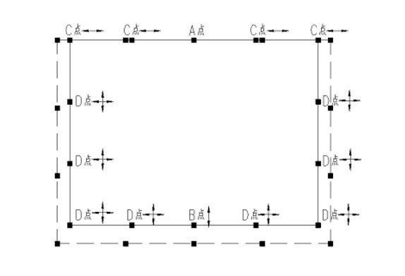
FIG. 1 Schematic diagram of the fixed embedded support layout of the space frame
Figure 1 assumes that point A is a fixed hinge. Under the action of temperature rise, the space frame expands to the dotted line position. The vertical support of point A, namely point B and point C, only has unidirectional horizontal displacement, while the remaining points, namely point D, have bidirectional horizontal displacement. In accordance with this principle, fixed hinge at point A, a unidirectional sliding hinge at point B and point C, and a double-directional sliding hinge at point D can be arranged to release the temperature stress. Under the action of the earthquake, point A and point B bear the X-direction horizontal force, and point A and point C bear the Y-direction horizontal force. The sliding direction stiffness generally takes 0~3kN/mm to release the displacement well. If the main mode is horizontal slip, the elastic stiffness in the sliding direction can also be appropriately increased, not more than 10kN/mm, so that the main mode is vertical vibration. For this kind of structure, if the above bearing selection is adopted, an independent calculation model can be used to simplify the design work. Considering that the horizontal stiffness and vertical stiffness of the substructure tend to be infinite, it is only necessary to input the bearing stiffness, which is a little different from the overall calculation results.
2. Independent column top beam support system
Separate column top-shelled beams are commonly found in indoor gyms. Generally, the gables are high, and the top and half height of the posts have concrete beam ties in one direction to separate the masonry wall and act as support for the parapet, while the cantilever columns are in the other direction.
This type of space frame support situation is more complex than the first two, it is recommended to calculate as a whole. Different from the second system, under the action of temperature, the side column in the long-span direction is a cantilever column, and the stiffness can be taken as an independent column value, in the beam direction can be regarded as infinite horizontal stiffness; The horizontal stiffness of the corner column is infinite in both directions because of the pull beam in both directions. If all fixed hinged supports are used, the space frame will be “hooped” by the column top pull beam under the action of temperature. However, if the support assumption scheme in Figure 1 is applied, the horizontal seismic force of individual columns will be too large, resulting in the excessive horizontal displacement of the column top.
At this time, it is recommended to arrange the support according to Figure 2. Point A is the fixed hinge, the temperature deformation is, the Y-direction stiffness is close to the cantilever column, and the deformation ability is strong, while point B releases the horizontal displacement in the beam direction, and does the fixed hinge in the direction of the cantilever column, forming a one-way sliding hinge, which can release the temperature stress and let more supports transfer the horizontal seismic force.
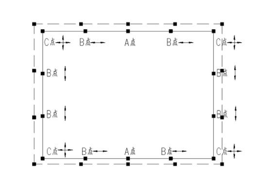
FIG. 2 Schematic diagram of space frame support arrangement of the tie beam set up on the top of independent column
In principle, it is suggested that the space frame and substructure of this support system should be modeled as a whole. The supported release should be accurately simulated with spring supports, and the support stiffness should be designed as an envelope by floating up and down according to the actual value. If the overall modeling is indeed difficult, the stiffness of the substructure and the support stiffness should be input into the model in series when designing the space frame separately. For point A, the stiffness of the substructure can be fixed in the X direction, and the stiffness of the cantilever column can be input in the Y direction. For point B, the elastic stiffness of the support can be input in the sliding direction, the stiffness of the cantilever column can be input in the fixed direction, and the sliding stiffness of the bidirectional support can be input in the C point. Compared with the overall modeling, the deformation and stress of the space frame support are basically consistent.
4. Inclined column support system
Three common space frame support systems have been discussed above, but other situations are often encountered in practical projects, such as slanting column support, especially when the horizontal stiffness of columns is large. In modeling, the slanting column top is assumed to be slanting fixed hinges, but the construction drawing is made into horizontal fixed hinges , resulting in the loss of horizontal force transmitted by the original slanting column to the space frame, which will cause the original tension string rod into compression rod and instability.
The space frame supported by the inclined column, it is often matched with the inclined curtain wall system, which needs to transmit the horizontal force of the curtain wall top to the space frame. At this time, it is necessary to pay attention to whether the horizontal force or diagonal force is transmitted by the connecting structure of the curtain wall and the space frame. In addition, the horizontal force of the curtain wall top will cause tension of many originally compressed upper chord bars. At this time, the envelope design should be carried out according to the horizontal force of the curtain wall top or not.
The wide application of the space frame structure provides the possibility for a change of architectural modeling. In the design of the space frame structure, we should focus on the selection of the support and ensure that the calculation assumption is consistent with the reality in order to achieve the coexistence of economy and security.


