3.2、space frame structure unit creation
(1) Use Revit to construct the curtain wall panel family to construct the space frame unit structure. The properties dialog box in the selected curtain wall insert sample file sets the space frame type. Since this paper adopts the quadrangular pyramid unit, the “rectangular”space frame is selected, and the four reference lines and reference primitives provided in the space frame are used as the reference position points for the creation of the structural unit. Use the “Point Element” tool to draw a reference line, select a point entity on the reference line, use the “Circle” button to center on this point, draw a circle with the radius of the member, and use the “Create Shape” in the panel Model the upper and lower chord elements.
(2) Establish the structural web after drawing the upper and lower chords. For the convenience of drawing graphics, the 2D view model is converted into a “3D view”. Use point primitives to create the vertices of the quadrangular pyramids of the web. On the vertical plane of the point primitives, set the reference line according to the height of the quadrangular pyramids, and modify the height parameters of the reference lines according to the height of the webs. Draw a bird’s eye view reference line, and use the chord element to draw the web knot.
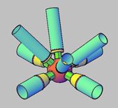
(3) Construct the solder ball model. Draws the center of the circle on the horizontal reference plane in the point primitive model. On the “3D View” interface, draw a cylinder or sphere with the center of the circle as the origin, and link the welding ball with the position on the “top chord unit”.
(4) After completing the space frame division of each component structure, load the created “chord element”, “welding ball element” and “web bar element” into the conceptual body model, and use the “pattern filling” button to fill the “top chord element” into The upper surface of the conceptual volume, and the circular modification of the filling construction of the space frame is completed to complete the filling of the upper surface, and the lower surface of the conceptual volume is filled in the same way.
3.3、Application in engineering project acceptance
In the process of project acceptance, staff need to process massive amounts of data information, and the above data information is all information generated during the construction phase of the project. In the collection and processing of data information, staff will be under tremendous work pressure. For example, BIM technology can be applied in the acceptance process of construction projects, and the platform can be used to complete the collection, arrangement and sharing of information and data, so as to strengthen the effectiveness of data processing. While improving the quality of project acceptance, it can also ensure the efficiency of project acceptance. Staff no longer need to deal with a large amount of complicated data information, which effectively reduces labor costs and provides reliable data and information support for the effective implementation of subsequent tasks. In addition, the results of construction project acceptance fully reflect the performance of the construction project. The application of construction technology quality inspection methods in construction projects can ensure that the construction and construction height meet the engineering standards and requirements, and ensure the stability and safety of construction operations. At the same time, in the process of establishing the BIM database, managers can more conveniently and quickly Obtain data information at a certain point in time, carry out comparative analysis of project resource consumption, sub-item cost and other information, understand the specific situation of project construction, and enable managers to accurately grasp and understand the general situation of construction project profits, which can also maximize control Risk factors affecting project cost in project construction.
3.4、Improve the construction schedule plan settings
Lifting phase scheduling is similar to installation scheduling. Specify the object animation, link the plan schedule to the corresponding “Animation” application interface through the “Animation Matching” option provided by the “Task” tab list in the “TimeLiner” toolbar, and realize the steel space frame promotion stage animation interface and progress Planned match. The audio files under the video can be generated through the “audio software”, and the “video production software” can be used to post-process the video files to refine the construction simulation.
BIM technology meets the development trend of different architectural shapes in the future, reasonably integrates BIM technology with the existing cutting-edge technology and advanced equipment of steel structure, improves the precision, develops new ideas, innovative construction, and intelligent construction, which is conducive to promoting the construction industry flourishing.






 About Us
 2023-10-09


