


 About Us
 2022-01-25
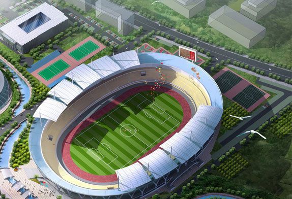
1. Steel Structure Stadium Project Overview
This project is a comprehensive sports facility, covering an area of 400,000 m², with a width of 400mm from east to west and a length of 1050m from north to south. There are 17 above-ground works in total, among which the steel structure installation works include the large-scale steel structure stadium canopy of the comprehensive stadium and the large-scale steel structure of the comprehensive stadium. 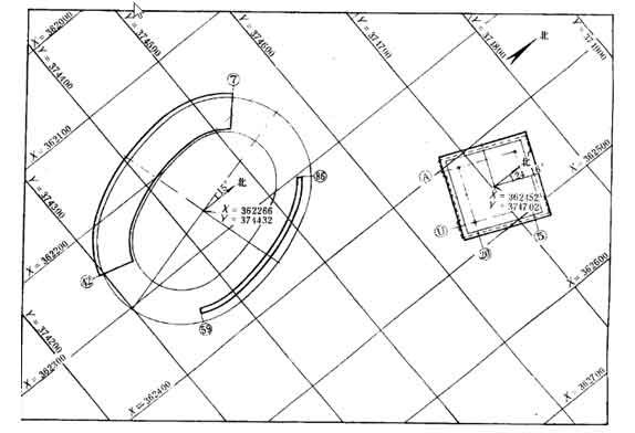 Figure 1-1 The floor plan of the comprehensive stadium and the comprehensive gymnasium
The comprehensive stadium has a construction area of 50,900 ㎡ and 60,000 seats. The plane is approximately oval, with a long axis of 276m and a short axis of 205.318m. It consists of eight arcs with radii of 95m, 105m and 243.818m. A, B, C, D, F,5 elliptical circles, the whole plane is divided into 96 column distances, 24 areas, each area has 4 column distances. This part is equipped with a large-scale steel structure canopy composed of a steel structure suspended peach truss (Figure 1-2, covering an area of 1130 square meters and 36 truss columns). Each column weighs 3.59t. There are 36 canopy trusses, the total length of the truss is 42m, the cantilever is 31m, and each truss weighs 18.5t. The tail is held by a large steel tie rod, which is 25.43m long and weighs 6.5t. The components such as the truss and tie rods are all welded structures, high-strength bolts are used to connect the truss column and truss, and steel door bolts are used to connect the truss and the upper part of the tie rod. The elevation is 20.91m, the upper chord of the canopy truss has a slope of 1/40, the front elevation is 26.52m, and the rear elevation is 25.65m. The material of the canopy steel structure is Q235 steel. The canopy has steel purlins and rafters on the upper chord and rafter structure on the lower chord. Ceiling structure. Tonghe ceiling steel structure is connected with a truss by common bolts. There are 4664 steel members in the whole cantilever, totaling 1512.78t. There are 12,000 sets of high-strength bolts and 15,000 sets of common bolts.
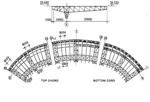 Figure 1-2 Comprehensive stadium canopy structure plan
The comprehensive gymnasium is approximately square in plan, with a construction area of 21,200 ㎡, 8,000 seats, a building plane size of 100.65m × 94.5m, a reinforced concrete column spacing of 5.8m, a roof surface of 100.8m × 100.8m, a large-scale steel structure flat space frame, The space frame is a four-column fulcrum and an orthogonal square steel high-strength bolt structure. The distance between the steel columns is 67.2m, the outreach of the space frame is 16.8m, the height of the space frame itself is 5.5m, the space frame spacing is 4.2m, and the coverage area of the space frame is 1016㎡. The entire space frame is composed of 624 unit trusses, which are welded structures and are divided into three categories: I, II, and III. Among them, there are 96 pieces of 14 types of I-connected trusses, 92 types of II-connected trusses, 480 pieces, and 19 of III-connected trusses. There are 48 kinds of trusses, the heaviest unit truss is III-5, weighing 4.105t, and the rest are all within 2.31t. The unit trusses are connected with high-strength bolts. The upper string of the space frame is provided with a roof structure composed of thin-walled steel, which is composed of uprights, purlins, and rafters. The purlin hoop is 4.2m, and the heaviest is 118kg. The lower string of the grid frame is provided with a ceiling structure composed of thin-walled steel and ordinary steel. The ceiling is composed of hanging rods, large keels and middle keels. The heaviest large keel weighs 116kg.
The whole space frame is placed on 4 steel columns made of steel pipes, and the space frame are connected by spherical hinges through the column caps. The outer size of the steel column is 2.6m×2.6m, the outer diameter of the steel pipe is 530mm, and the wall thickness is 14mm. The length of the steel column is 19.82m, the weight of a single column is 33.05t, the elevation of the top of the column is 15.46m, the elevation of the lower chord of the space frameis 20.00m, and the elevation of the upper chord is 25.50m.
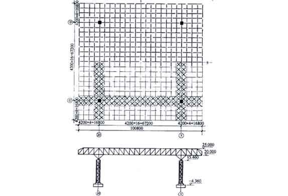
Figure 1-3 Comprehensive gymnasium steel structure plan
2. Stadium cantilever canopy installation method
1) The canopy structure of the stadium adopts the method of internode installation. According to the single weight of the canopy truss, the installation height and the plane size of the steel structure, two 12t tower cranes are selected, and the double-machine lifting truss is used for small components. 2 tower cranes are installed separately. The tower cranes are located in the range of (7-42)-axis, one stands in the field, and its track center is 5m away from the (A) axis; the other one stands outside the field, 8m away from the (F) axis. Since the building axis is arc-shaped, the track of the tower crane is also arc-shaped, and its curvature is consistent with that of the building axis. The length of the horizontal arm of the tower crane is 30m, the vertical height is 35m for one set, and 40m for the other, and the height difference between the two tower cranes is 5m. In addition to meeting the installation height, the boom of the two tower cranes can also be used. Do not interfere with each other during installation.
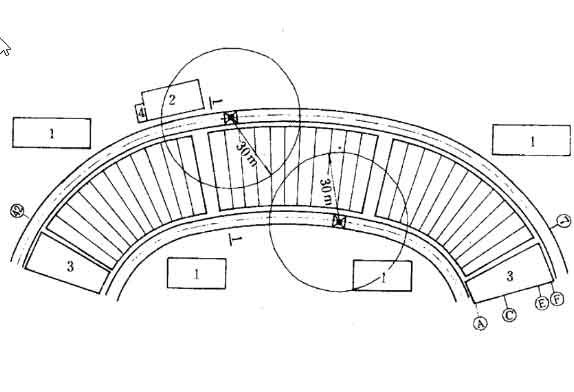
Figure 2-1 The floor plan of the installation stage of the cantilevered steel structure
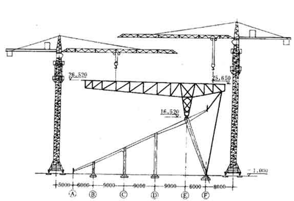
Figure 2-2 Location map of tower crane in the installation stage of cantilevered steel structure
2) The gymnasium space frame adopts the high-altitude bulk process. According to the plane position of the space frame unit and the single D axis of 19.60m, the position weight, 2 tower cranes are selected to install the space frame structure components. The position one is 19.6m away from the (D) axis, and the other is 20.30m. The length of the horizontal arm of the two tower cranes is 50m, and the height of the tower is 40m and 45m respectively.
The tower cranes for stadiums and gymnasiums are first used by the civil engineering unit during the civil construction stage and then handed over to the steel structure installation unit after the reinforced concrete frame structure is completed. After the steel structure is installed, it will still be handed over to the civil engineering unit for use.
(3) The ground assembly work of the steel structure is carried out with a rubber-tired crane. Adopt 40t and 20t wheels One tire crane each
(4) The friction surface of high-strength bolt joints is treated by on-site sandblasting, and a portable sandblasting machine is used to
The sand is natural river sand with a diameter of 0.5-3mm, and the content of quartz particles is more than 50%.
(5) The electric welding machine adopts 8 AC electric welding machines with a capacity of 30kVA.
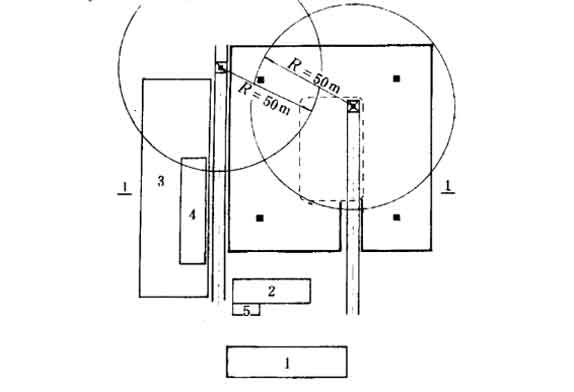
Figure 2-3 Layout plan of space frame steel structure installation stage
3. Installation sequence
(1) The installation sequence of the bleacher canopy steel structure
The canopy plane is divided into three sections by expansion joints. When installing, start from a room with full support in the middle of each section, and install it sequentially on both sides. There are two advantages in this way. First, after the full support connects the two trusses, the structure can quickly form a stable whole.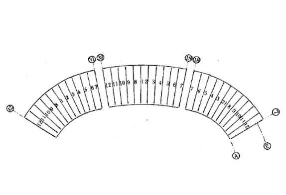
Figure3-1 Installation sequence diagram of canopy steel structure
(2 )Installation sequence of space frame steel structure
As shown in Figure 3-2, 3-3, Install the main truss members on both sides of the ⑤ axis and the ⑤ axis first, connect them with the column to form a stable whole and then install them sequentially from the middle of the E axis and the U axis to both ends. In this way, the calibration work of the space frame structure becomes very simple, and the installation deviation can be minimized. Before the space frame of the gymnasium is not integrated, it cannot bear the load including its own weight, and temporary support points must be set up. According to the weight of the space frame and the installation sequence, a total of 5 temporary support points are set. The supporting point is designed with a scaffolding steel tube in full-length scaffolding, which is the same as the temporary fulcrum of the stadium. The temporary support point load is 300kN, and the 30t lead screw jack is used. The support points on the steps of the stands are reinforced with sleepers below them. The position of the support point is set directly below the node of the space frame, When erecting, use a wire pendant to correct the vertical deviation of not more than 50mm.
Removing the support point is an important process in the installation of the space frame, which must be attached with great importance. The following must be done before dismantling:
(1) The elevation of each lower chord node of the fulcrum of the space frame has been checked and recorded;
(2) The final tightening of the high-strength bolts has been checked and qualified;
(3) All ordinary bolts on the support and cover plate have been inspected and passed;
(4) A scale with a scale has been set on the temporary support point, and the zero position of the scale has been aligned with the lower skin of the lower string angle steel of the string frame;
(5) The stroke of the jack has been determined according to the design deflection value, and adjusted to the position where the downward pressure is the descending position.
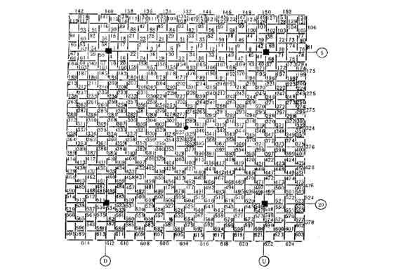
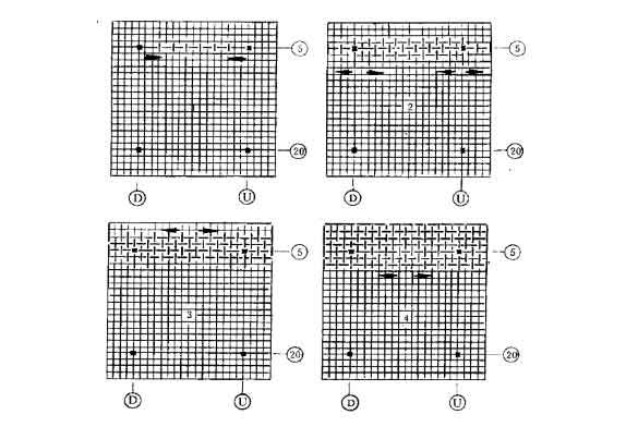
Figure3-2 Installation sequence diagram of space frame steel structure


