


 About Us
 2022-12-09
1. Steel Structure Sports Hall Project Overview
The expansion project of Jian’ou No. 1 Middle School is supporting sports venues (indoor prefab gymnasium, swimming pool). The design theme of the “two halls” is to spread branches and leaves, and the feelings of roots are in line with the meaning of the school’s spread of branches and leaves, and peaches and plums are all over the world. To the hometown, the roots of the alma mater feelings. The new gymnasium has a construction area of 5353m2, with a 150m circular track and a 60m straight track indoors, which can accommodate 4 classes for physical education classes and large gatherings at the same time; the construction area of the swimming pool is 2911m2. It is a 25m x 50m standard swimming pool with A constant temperature water circulation system that can be used for education and teaching and large-scale swimming competitions throughout the year.
The swimming pool and gymnasium of this project use space and a truss structure system. The swimming pool is equipped with 25 circular tubular columns, and 13 main trusses, and the truss roof and the circular tubular columns are connected by welding. The steel columns and truss members of the swimming pool are all made of circular tube sections. The sections of the steel column members are P450 mm x 16 mm; mmP114 mm x 6 mm etc. The roof purlin components are made of square steel pipes, with a cross-section of B160 mm x 80 mm x 6 mm x 6 mm; the gymnasium truss roof and the concrete columns are connected by supports, the trusses are of inverted triangle type, and the steel pipes are connected by intersecting welded joints. The structural components of the gymnasium are all round tubes, and the cross-sections of the components are P402 mm x 16 mm, P377 mm x 16 mm, P351 mm x 16 mm, P245 mm x 12 mm, P219 mm x 12 mm, P209 mm x 12 mm, P180 mm x 10 mm, P168 mm x 8 mmP159 mm X 6mm, P114 mm X 6 mm, P89 mm x 6 mm, etc. Figure 1 is the overall rendering of the “Double Pavilion”, and Figure 2 is the axonometric view of the overall structure of the “Double Pavilion”.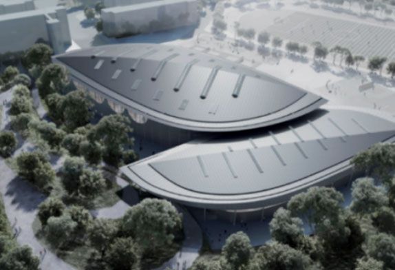
FIG. 1 Steel Structure Stadium Overall rendering
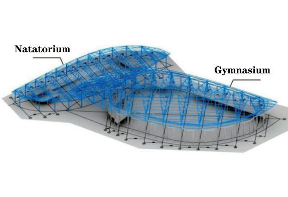
FIG. 2 Overall structure axonometric diagram
2 Construction plan for truss installation
2.1 Overview of the on-site installation scheme
Typical steel truss construction and installation methods mainly include the following: high-altitude bulk method, strip or block installation method, integral lifting method, high-altitude sliding method, integral jacking method, folding and unfolding installation method, integral hoisting method, climbing Dome construction method (Pantadome system), cumulative lifting method, etc. The swimming pool and gymnasium of this project are mainly of pipe truss structure, the swimming pool adopts a single-piece truss; part of the main truss of the gymnasium is an inverted triangular section. The section size of the main truss is 6.95 mx11.0m at the maximum position of the inverted triangular truss. Considering the limitation of transportation conditions, in order to improve transportation efficiency, it is planned to adopt the method of processing the parts in the factory, transporting them to the site and assembling them in sections, and then hoisting them into place for installation. Since part of the trusses of the gymnasium adopts pre-embedded anchor bolt nodes, the supports are assembled on the truss during the ground assembly stage of the truss-hoisting.
2.2 truss assembly
The erection and splicing of the tire frame Considering the large self-weight of the segmented unit, in order to prevent the occurrence of large initial defects and affect the later assembly, the tire frame should be welded by I-shaped steel with a small cross-section, and the assembly site must be hardened in advance. Processing, the hardness and flatness of the site must meet the requirements before the welding operation; the tire frame should be set to avoid the position of the nodes, that is, the nodes should be arranged in a staggered manner, and at the same time, it should meet the welding workspace of the welder. The tire frame must ensure that the level error of the upper opening of the tire frame is within +1mm. In order to facilitate the lifting and installation of the whole truss, from the perspective of construction mechanics, the layout of the tire frame should be strictly in accordance with the construction drawings. During this period, technicians and safety officers should be supervised to avoid rework accidents, and timely acceptance and signature of supervision and acceptance signatures are required, and various construction specifications and systems should be strictly implemented. In order to prevent uneven settlement of the tire frame, a settlement observation point should be set up beside the tire frame as the inspection basis for platform settlement. The cross-section of the tire frame is HN400 mm X 200 mm x 8 mm x 13mm, the height of the horse is 0.8m, and the distance between the tire frames is 6m. The height of the tire frame horse stool is 0.8m. The height of the tire frame from the ground to the top is 8.8m, the width is 11m, and the distance between the tire frames is 6m.
2.3 The truss assembly method and process
The main truss of the swimming pool is assembled by plane, and the main truss of the gymnasium is assembled by vertical assembly. The detailed process is as follows.
2.3.1 Vertical truss assembly
The truss vertical assembly process is shown in Figure 3.
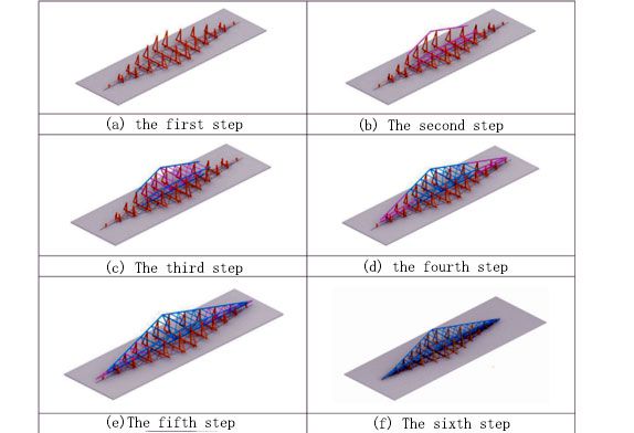
Figure 3 Flow chart of vertical assembly of truss
The main operation steps are as follows:
(1) Draw the line size of the truss on the rigid working platform, including the center line of the upper and lower chords and the tongue and groove lines at the ends; pay attention to the camber of the truss when drawing the lines. After the truss line is drawn, set the assembled tire frame according to the drawn line, assemble the truss on the assembled tire frame, and add a pad under the truss support position.
(2) Install the middle section truss chord and fix it by spot welding.
(3) Install the middle web member of the truss and the chords at both ends, and fix them by spot welding.
(4) Install the web bars at both ends of the truss and fix them by spot welding.
(5) Install the middle web of the truss at both ends and the chord at both ends, and fix them by spot welding.
(6) Check the assembly accuracy and error of the truss. If the assembly size error is large, it should be adjusted in time to meet the requirements. After the inspection is qualified, the welding should be carried out. The small error should be adjusted in time during the welding process, and the error should not be increased during welding. After the welding is completed, the weld quality inspection should be carried out on time, and the truss assembly at this stage is completed.
2.3.2 Plane truss installation
(1) Draw the overall line size of the truss on the rigid working platform, including the center line of the upper and lower chords and the tongue and groove lines at the ends; pay attention to the camber of the truss when drawing the lines. After the truss line is drawn, set the assembled tire frame according to the drawn line, assemble the truss on the assembled tire frame, and add pads under the truss support position.
(2) Install the truss chord and fix it by spot welding.
(3) Install the truss web and fix it by spot welding.
(4) Check the assembly accuracy of the truss, and after passing the inspection, carry out welding.


