About Us
 2022-08-10
1. Large Diameter Dome Roof Project Overview
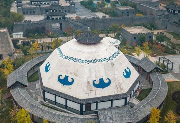
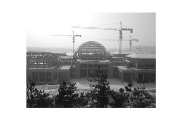
1.1 The roof of the Bingsheng Palace in Sunzi Cultural Park is an archaized steel structure building. The outer contour of the exhibition hall is a double-slope roof, with a magnificent overall shape. The middle dome is a Kevite welded ball space frame structure with a diameter of 36m, the large diameter dome welded ball space frame system looks very great, and the bottom elevation of the ball support is 20.050m. The steel skeleton of the sloping roof is φ 245*12 steel pipe, which is an archaize slope roof shape.
1.2 The position of the middle dome roof is a welded ball space frame structure, the material is Q235B, and the total weight of the space frame is about 100 tons.
2. Welded Ball Space Frame Dome Roof Construction Difficulties
There are many types of welded balls and rods, the part numbers of the components are clear and accurate, and the delivery management is carried out strictly according to the dome roof construction requirements.
The site is narrow and the reinforced concrete structure around the space frame has been completed, and there is no reserved hoisting machinery approach route. The pole parts of the welded ball space frame can only be hoisted by a tower crane, and the hoisting performance of the tower crane can only meet the hoisting of a single rod.
The measurement and positioning accuracy of the ball joint is extremely high. Once the deviation occurs, it will cause systematic deviations in the size of the rod, the gap between the welds, and the welding joint process parameters, and every time the lifting will cause the change of the spatial coordinates of the component, so it must be re-measured and the coordinate system must be rebuilt.
It is difficult to control the lifting process. During the lifting process, the components must be effectively controlled to ensure that the spatial position of the components does not deviate greatly and that each lifting point is uniformly stressed. 2.5 During the dome building space frame lifting process, the position conversion of the lifting point must conform to the characteristics of the structural force to ensure the safety of the structure during construction.
2. Large Diameter Welded Ball Dome Overall Construction Deployment
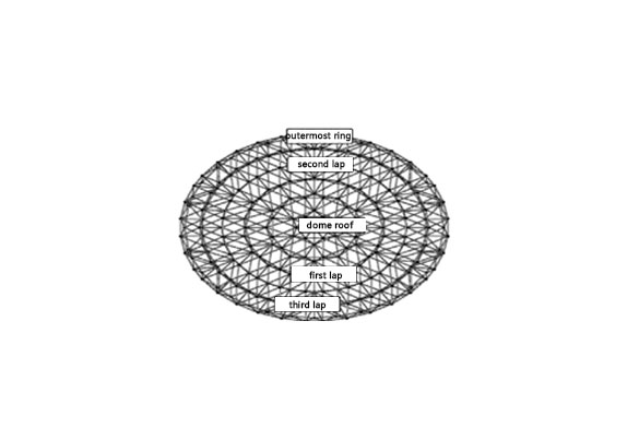
After the space frame dome is assembled and welded on the ground, it is lifted with a 12m long single-leg pulling rod. After the first ring of the space frame is lifted to the installation level of the space frame, the first ring of the space frame is assembled and welded. After the first circle of the space frame is completed, the second circle of the space frame and the third circle of the space frame are assembled and lifted, and the outermost ring of the reserved mesh frame is assembled and welded after being lifted into place. When lifting, a temporary lifting bracket is welded at the lower part of the third ring of the space frame. Using the temporary lifting bracket and the embedded part of the support, the assembled and welded Kaiweite-type space frame is lifted to the corresponding elevation, and finally, the outermost ring space frame is assembled in bulk and welding.
Kavite type space frameunit branch diagram
4 Dome Roof Construction Process And Key Points Of Operation
4.1 Dome roof construction process construction preparation → ground layout → space frame dome welding ball positioning →space frame dome assembly and welding → single-leg pulling rod installation → single-leg pulling rod first lift → space frame first circle welding ball positioning → The first round of assembly and welding of the space frame → the second lifting of the single-leg pulling rod → the second round of welding ball positioning of the space frame → the second round of assembly and welding of the space frame → the third lifting of the single-leg pulling rod → the third round of welding of the space frame ball positioning → assembling and welding of the third circle of the space frame → lifting the single-leg pull rod for the fourth time → welding the temporary lifting bracket → lifting the chain hoist → bulk and welding the outermost ring of the space frame → removing the temporary lifting bracket.
4.2 Operation points
4.2.1 Steel structure dome-shaped roof construction preparation
(1) Before the space frame is assembled, first measure the positioning size of the embedded parts of the support, the axis and elevation of the embedded parts, and the flatness to meet the installation requirements.
(2) The assembly and welding site is leveled, and the pre-embedded construction of the welding ball positioning rod and the single-leg pull rod foundation is completed.
4.2.2 Lofting and assembling of the space frame dome
(1) Establish a three-dimensional space coordinate system, use the theodolite to measure the horizontal projection position of the welding ball on the ground embedded parts, and play the crosshairs.
(2) Weld Ø159*8 steel pipe on the embedded part of the welding ball positioning rod foundation, correct the verticality, and after measuring the elevation, spot-weld the welding ball on the positioning rod.
(3) Start welding after the space frame dome is assembled.
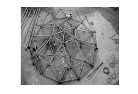
Welding of space frame roof dome
4.2.3 Installation of one-legged puller
(1) After calculation, 6 steel pipes with a length of 14 meters and Ø273*16 are set up in the second circle of the space frame to make single-leg pulling rods, which can be arranged in the dome of the space frame to meet the installation requirements. The layout diagram is as follows:
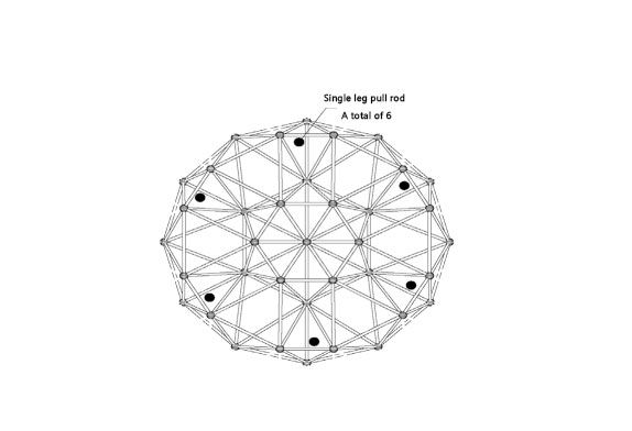
Positioning diagram of one-legged bar puller
(2)The lifting ears welded in 4 directions at the top of the single-leg pulling rod are used to hang the chain hoist, and the chain hoist is used as a lifting device to lift the grid;
(3)The top of the single-leg pulling rod is tied with cable wind ropes in four directions. The lower port of the cable wind rope is fixed on the concrete structure with a post-embedded piece. After calculation, the cable wind rope uses a Ø16 steel wire rope.
(4)The single-leg pulling rod is installed by a tower crane.
4.2.4 Lifting the single-leg pulling rod
(1) Acceptance shall be carried out after the single-leg pulling rod support and installation is completed. The acceptance content includes whether the wire rope is tensioned, the verticality of the pulling rod, and the tonnage of the chain hoist.
(2) Before the promotion, conduct operation drills, unified command, unified password, and synchronous promotion
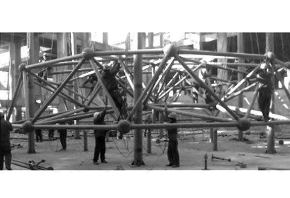
Single-legged rod lifting diagram
4.2.5 Installation of the first circle to the third circle of the space frame
(1) After the space frame is raised to the corresponding elevation, measure and correct the spatial position of the space frame.
(2) The simple lifting bracket is used for the installation of space frame welding balls and rods. Install the lower layer of the space frame first, and then install the upper layer of the space frame.
(3) After the installation and welding of the first ring of the space frame is completed, lift it up, and start to install the second ring of the space frame, and use the same method to complete the installation and welding of the third ring of the space frame.
4.2.6 Installation of temporary lifting support
(1) The function of the temporary lifting bracket is to lift the Kaiweite type space frame from the ground to above the level of the embedded part of the support when the outermost ring of the space frame is not installed and does not affect the installation of the outermost ring of the space frame.
(2) After the installation and welding of the third circle of the space frame is completed, the fourth lifting of the single-leg pulling rod is carried out, and the lifting height is 2.5m.
(3) It is calculated that two Ø140*6 and three Ø194*10 steel pipes are used for the temporary lifting bracket to meet the requirements. The upper ports of the steel pipes are all welded on the welding balls, and the lower ports are connected to the Ø203*10 steel pipes and welded with lifting ears.
4.2.7 Hand-pulled hoist lifting and installation of outermost ring components of space frame
(1) After the temporary lifting bracket is installed and welded, the chain hoist is lifted. The upper end of the chain hoist hangs on the lifting lug welded by the embedded part of the support.
4.2.5 Installation of the first circle to the third circle of the space frame
(1) After the space frame is raised to the corresponding elevation, measure and correct the spatial position of the space frame.
(2) The simple lifting bracket (Patent number: 201210437479) is used for the installation of space frame welding balls and rods. Install the lower layer of the space frame first, and then install the upper layer of the space frame.
(3) After the installation and welding of the first ring of the space frame is completed, lift it up, and start to install the second ring of the space frame, and use the same method to complete the installation and welding of the third ring of the space frame.
4.2.6 Installation of temporary lifting support
(1) The function of the temporary lifting bracket is to lift the Kaiweite type space frame from the ground to above the level of the embedded part of the support when the outermost ring of the space frame is not installed and does not affect the installation of the outermost ring of the space frame.
(2) After the installation and welding of the third circle of the space frame is completed, the fourth lifting of the single-leg pulling rod is carried out, and the lifting height is 2.5m.
(3) It is calculated that two Ø140*6 and three Ø194*10 steel pipes are used for the temporary lifting bracket to meet the requirements. The upper ports of the steel pipes are all welded on the welding balls, and the lower ports are connected to the Ø203*10 steel pipes and welded with lifting ears.
4.2.7 Hand-pulled hoist lifting and installation of outermost ring components of dome-shaped roof space fame
(1) After the temporary lifting bracket is installed and welded, the chain hoist is lifted. The upper end of the chain hoist hangs on the lifting lug welded by the embedded part of the support.
(2)After lifting to the corresponding elevation, measure and correct the spatial position of the Kaiwitt-type space frame.
(3)Install the welding ball at the support first, then install the rod between the lower rod of the outermost ring of the space frame and the welding ball of the support, and finally install the upper rod of the outermost ring of the space frame.
(4)The outermost ring members of the spaceframe use tower cranes as the main hoisting machinery, and are bulk loaded at high altitudes.