


 About Us
 2022-11-16
1 Conference center project overview
The AU conference center project is located in Addis Ababa, the capital of Ethiopia. It consists of a 21-story office building with a building height of 99m, a conference hall with a long axis of 63m, a conference hall with a short axis of 57m, and a podium with four floors (figure 1,2). The proposed site belongs to the plateau phase mountainous landform unit. The terrain in the site is high in the northeast and low in the south and low in the west, and there is a drainage ditch flowing from north to south on the west side of the site. The groundwater of the site is mainly pore-type phreatic, which occurs in layers ②~5 within the investigation depth of the site. It is generally rich in water and is a weak aquifer. (5) Although weathered fractures are developed in the strata, they are all filled with argillaceous material, basically water-free and relatively water-resistant. Layer 1 is a weak aquifer filled with stagnant water in the rainy season. In order to solve the problem of earthquake resistance and plane length, high-rise office buildings and skirt houses are completely disconnected by setting settlement joints (and shock-proof joints). The grand conference hall and the podium area are completely separated in design and are only flexibly connected through the steel structure corridor. Here only introduces the structural design of the large conference hall.
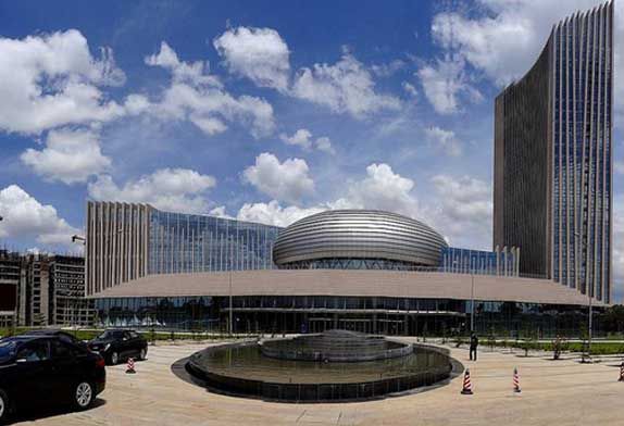
FIG. 1 A panoramic view of the AU Conference Center
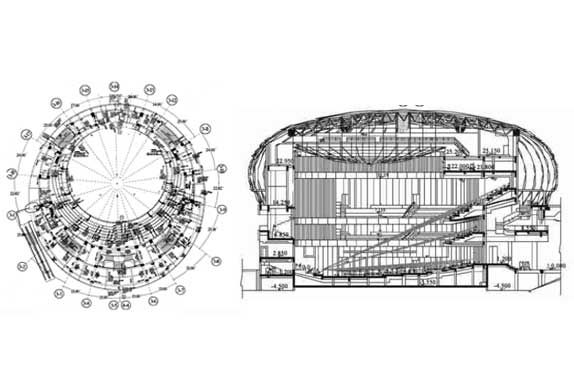
FIG. 2 Structure plan and section
2 Structural system
The grand conference hall section consists of 1 basement and 4 superstructures (partially mezzanine). The plane of the building is elliptical, and the elevation shape is an elliptic spherical space curved surface. The reinforced concrete structure is used as the supporting platform of the surrounding steel structure support system and the roof steel structure single-layer reticulated shell. The periphery of the structure provides shelving points for the roof trusses of the adjacent podium corridor. The cross-section of column members varies from 700×700~1000X1200, mainly based on the layout of the building, and determined according to the principle that the compressive stress of the column section is permanently flat in the normal use stage. Due to the uneven layout of the building plane, there are many cantilevered parts with different lengths, so the cross-section of the primary and secondary beams is quite different. For aseismic consideration, the large conference hall structure is completely separated from the podium structure except for the shelving point of the podium corridor truss and four columns in the third part of the floor. A finite sliding bearing is set at the shelving point of the podium truss, and the limit is determined according to the elastic-plastic relative deformation under the action of rare earthquakes. In layer 3, four columns are divided along the diameter, and seismic joints are set in the middle to meet the requirements of independent deformation. In the structural design, the large conference hall is composed of three parts: the main body reinforced concrete structure, the lateral surrounding steel structure support system, and the steel structure truss stiffening single layer net shell on the roof. The roof has a plane span of about 40m and adopts a simple steel structure with a single reticulated shell (see Figure 3). In order to control the stability of a single-layer reticulated shell and reduce the amount of steel used in the structure, three stiffening trusses are arranged in the short direction of the shell and one stiffening truss is arranged in the long direction. The stiffening truss is in the form of a square pyramid. The roof is reinforced with a single reticulated shell while providing support for the roof lighting and maintenance track inside the grand conference hall.
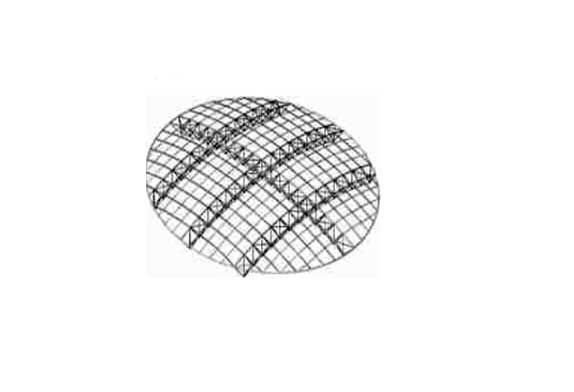
FIG. 3 Truss stiffened single-layer reticulated shell roof
The lateral steel structure support system of the large conference hall is formed by three sections of bus wire splicing around the ellipse, and the main rib beams with curved periphery are all welded H-beams. The lower part of the main beam is connected to the peripheral beam of the layer 3 planes of the main reinforced concrete structure through the V-shaped brace formed by the middle 180×8 steel pipe, and its upper part is connected to the reinforced concrete ring beam at the top of the main concrete structure. In the lateral steel structure support system, a box stiffening ring beam (300×300×20) is set separately at the shelving place of the peripheral steel structure truss to provide enough support and reduce the influence of the shelving truss on the lateral steel structure support system. The reinforced concrete ring beam is arranged on the top of the reinforced concrete main structure, and the surrounding steel structure support system and the roof steel structure single-layer reticulated shell are connected with the roof reinforced concrete ring beam in a relatively connected way. Each part of the structural system is mutual, and independent, and can be reliably connected to form an organic and unified overall structural system.


