


 About Us
 2023-02-03
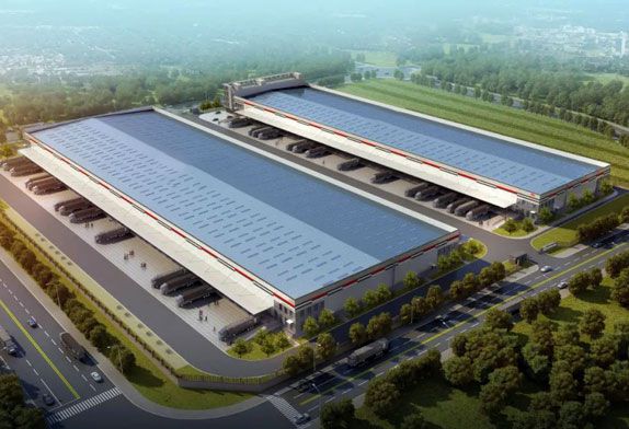
A large-span assembly plant building covers an area of 20,976m, with a total construction area of 26,966m. The span of the house is 66m+118m+76m, the depth is 80m, the elevation of the lower chord of the roof is 26.0m, two suspension cranes with a lifting capacity of 15 and one lifting capacity of 30t are installed, and the structural scheme of the space frame roof combined with the gate anti-beam is adopted for the hangar hall. There is a three-story annex at the inner back, 185m long, with a column net of 9m (10m, 12m) x 6m. There is a basement under the annex. The factory building can accommodate 4 large aircraft, and it will be one of the factory buildings with the largest suspension crane tonnage in China after completion.
1 Structural scheme
1.1 Structural scheme selection
The factory building has the following main features:
1)The factory building has a large structural span, high height, and high safety level;
2)The basic seismic intensity of the proposed site is 8 degrees, the site soil category is Class 1, and the seismic fortification intensity is high;
3)The building of the factory is equipped with two suspension cranes with a lifting weight of 15t and one with a lifting weight of 30t. The suspension cranes have a large tonnage, among which 30 suspension cranes are first used in the domestic plant structure;
4)The height of the building to be built is subject to the height limit requirements of the airport airspace, and the selection of the structural scheme should be combined with the above characteristics. At the same time, the plant has a large opening on one side, similar to the hangar structure, so the choice of the structural scheme at the gate is the key to the design. The available structural schemes include multi-stage primary and secondary steel truss systems, space frame structure systems, cable-stayed truss structure systems, arch gantry structure systems, etc., among which the cable-stayed scheme and gate arch scheme cannot be implemented due to the proposed site conditions of the workshop. The advantage of the space frame structure scheme is that the space frame space is stressed, the overall rigidity is large, the amount of steel used is less than that of the plane structure, the seismic performance is better, it is more suitable for high-intensity areas, and the design and construction experience is relatively mature. The disadvantage lies in the on-site construction The amount is large. The advantages of the multistage primary and secondary steel truss scheme are that the structural force is clear and reliable, and the component layout is simple. The horizontal and horizontal multistage trusses are the external support system of each other, which is overall better than the unidirectional plane force system, and the joint and lifting points of the truss can be arranged flexibly according to the working face of the hanging equipment, which is convenient to manufacture and install, and the construction technology is mature. Its disadvantage is that the overall stiffness is slightly lower than that of space frame structure, the steel used slightly has good seismic performance, which is more suitable for high-intensity areas, and the design and construction experience is relatively mature. Its disadvantage is that the construction volume is larger. The integrity is better than the unidirectional plane force system, and can flexibly arrange the truss joints and lifting points according to the requirements of the hanging equipment working face, convenient production and installation, and mature construction technology, its disadvantage is that the overall stiffness is slightly lower than the space frame structure, the amount of steel is slightly larger.
Based on the above analysis and a large number of calculation analyses and comparisons, this project adopts the structural scheme of space space frame roof combined with the gate back beam. This scheme has good spatial overall performance, the vertical stiffness of the roof is large, the force transmission is clear and reasonable, which is conducive to seismic resistance, and the steel quantity index is the best in construction. There are many similar projects in China with mature experience, processing and installation technology.
1.2 Roof structure layout
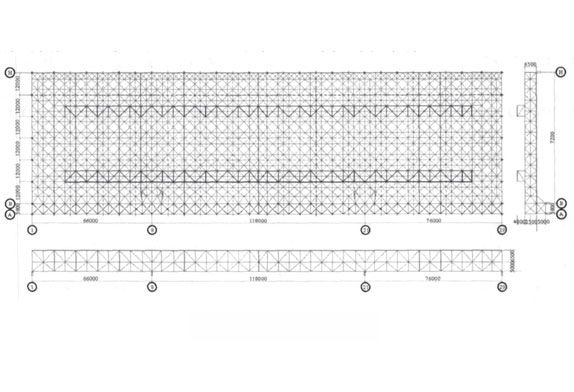
The roof of the steel structure workshop hall adopts a three-layer obliquely placed square pyramidal steel space frame with welded hollow ball nodes, the space frame size is 6.0m×6.0m, the space frame thickness is 6.5m, and the lower chord elevation is 26.0m. The gate anti-beam adopts a three-layer steel space frame. The girder height of the gate is 11.5m, and the lower chord elevation at the gate is 21.0 m1. The main stress member of the hangar roof steel structure adopts round steel pipes, and the material is Q355B. Steel Figure 1 is a planar section view of the space frame roof
The edge banding truss is set around the diagonal quadrangle pyramidal space frame, and the upper and lower strings of the net frame correspond to the depth direction of the two central columns with three straight bars 1. The calculation and analysis show that this is similar to adding two central trusses, which can strengthen the roof stiffness and reduce the peak internal force obviously. Because the roof of the building has a skylight, the skylight frame is directly used as the stress component of the roof structure in the design.
space frame roof cover
2 Space frame roof node design
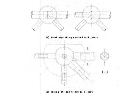
Roof joint design is an important link in the structural design of this project. The space frame roof of this project adopts an all-welded ball space frame, and the joints are under great stress, and the internal force of many members exceeds the requirements of the welded ball bearing capacity calculated according to the current space frame regulations. The design mainly adopts the following two methods to deal with it:
1)Steel pipes run through the ball joints, mainly used for the chord bearing force, and the rods can be butt welded in the ball. If the pipe diameters are different, butt steel plates can be added;
2) The combined joint of the plate and the hollow sphere is used in the case where there are three or the internal force of the five root members is very large in one joint. These two methods have been used maturely in previous projects. Although the construction is a little troublesome, they avoid the use of steel trusses and give full play to the cross-sectional advantages of round steel pipes, thus greatly saving steel consumption and achieving better overall benefits.
For the above two joint forms, we carried out finite element analysis and scale joint test (the situation of joint analysis is published in another paper). The finite element analysis results show that both of the two joint forms can meet the design requirements, and when there is enough safety reserve, the bearing capacity of the steel pipe through the welding ball joints is greatly improved compared with the ordinary welding ball. In particular, the failure mode of the point in compression season is the failure of the rod before the ball, and in general, the abdominal rod has little influence on the through ball node.


