


 About Us
 2023-06-14
1 Project Overview
The joint workshop of Xuchang cigarette factory is a comprehensive tobacco joint production plant consisting of more than thirty different functional rooms, such as formula elevated warehouse, silk making workshop, vacuum damp room, pre-matching cabinet room, etc. The total construction area is 137,154m2, of which 136,435m2 is above ground construction area and 719m2 is underground corridor construction area, The joint workshop is a large C class comprehensive industrial building with fire resistance class I, roof waterproof class II and underground engineering waterproof class II. Roof waterproof grade II, underground engineering waterproof grade II. The building height is 23.4m, the seismic intensity is 7 degrees, and the design service life is 50 years.
2 Space frame construction
2.1 The starting point and flow direction of the space frame construction are determined
Space frame structure installation flow direction: Ⅰ-C area is constructed from west to east, i.e. 1-8 axis → 1-31 axis; Ⅲ-E, D area is constructed from east to west, i.e. 3-31 axis → 3-1 axis. Roof steel beam system installation flow: Ⅱ-A area 2-1 axis → 2-9 axis; Ⅲ-F area 3-C axis → 3-Q axis.
2.2 Space frame construction flow
Space frame construction flow: ground laying sliding track → erecting sliding bracket → converging with general contractor, supervisor, space frame installation unit on-site steel structure row frame column handover acceptance (axis, space frame installation elevation, buried parts position, etc.) → a column distance mesh frame overhead bulk → bracket forward sliding a column network → next column distance space frame overhead bulk → repeat bracket sliding and overhead mesh frame bulk until the end of mesh frame installation. Roof beam construction process: on-site section steel and concrete handover acceptance (axis, section steel and concrete column top elevation, buried parts position, etc.) → local steel beam on-site assembly → steel beam lifting → horizontal support installation, forming a stable system → next beam lifting → sequential construction until steel beam and water support lifting is completed → steel purlin installation → roofing color plate installation.
2.3 Space frame installation
The space frame installation all adopts the construction method of movable full Fig.1 net frame structure installation schematic diagram of the hall bracket overhead bulk, the middle span a column net is installed at one time; the side span a column net is installed in two times.
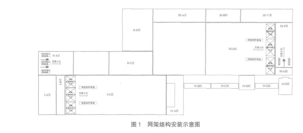
Fig. 1 Schematic diagram of the space frame structure installation
After the space frame bulk installation is completed, the normal assembly and installation can be carried out according to the high altitude bulk installation process. Installation process: ground assembly of ball rod components → lifting ball rod components with lifting equipment → aerial alignment splicing → after completing the mesh of a column network, adjust the axis of the support, elevation, mesh span deflection → temporary installation welding of the support → pan scaffolding (slip method installation) → repeat the above process until the end of the installation of the mesh. The ground assembly of the ball club component is divided into standard ball club and non-standard ball club for assembly. Standard cue: one ball two, one ball three, one ball four; non-standard cue: one ball one, one ball five. According to the design characteristics of the grid structure should also comply with the following points: two-span and three-span continuous structure assembling, continuous structure must be assembled simultaneously; assembling should start from the middle column, both sides synchronous assembling; according to the assembling plane.
3 Light steel structure construction
This project Ⅱ-A area and Ⅲ-F area are I-beam with solid web. Zone II-A is 72m long, 54m wide and 23.1m high, with main column spacing of 9m and main span of 22m and 32m. Zone III-F is 102m long, 35m wide and 23.1m high, with main column spacing of 9m and main span of 17m and 18m. Zone II-A adopts two 25-ton automobile cranes for double lifting, and Zone III-F adopts one 25-ton automobile crane for single lifting. The installation sequence of roof steel beams was taken to be installed span by span. Considering the error of civil construction, the steel beam is processed in the middle section in the factory first, and then the distance between columns is remeasured after the construction of civil steel columns, and then the beam section connected with steel columns is processed to correct the error.
3.1 Steel beam installation process
Approach of steel beam and acceptance of components → ground pre-assembly and inspection on site → preparation of lifting equipment → steel beams are lifted into position → temporary fixing of high strength bolts → review of column axis and verticality → final screwing of high strength bolts.
3.2 Steel beam ground assembly
Check the components before assembling the steel beam on the ground. If the deformation and defects of the components exceed the allowed deviation, they must be processed. Check the friction surface of the high-strength bolt connection, there must be no mud and sand and other debris, the friction surface must be flat and dry, and must not work in the rain. Ground assembling with oil-free sleepers to pad up the components, both sides of the components with wooden bar support to enhance stability. Before assembling, form an assembling platform with at least 4 supporting points, place all the solid web beams on the platform, splice them according to the drawing number, first use the high strength bolts to connect the initial screwing, and then use the force measuring wrench to tighten the final screwing after the inspection is accurate. And so on, the row of steel beams are all assembled, and then check the lifting point, alignment benchmark and centerline. The high-strength bolts used for connection shall be checked for the certificate of conformity and the torque factor shall be rechecked according to the factory batch number. The length and diameter shall meet the design requirements. High-strength bolts should be free to penetrate into the hole, no forced knocking, no gas cutting hole expansion. The direction of penetration should be consistent. High-strength bolts are tightened from the center outward by electric wrenches with kilogram number, and the tightening is divided into initial and final screwing. The initial tightening should be 50% of the final tightening. When there is a gap on the contact surface of high-strength bolts, the gap of less than 1.0mm can not be dealt with; 1.0mm~3.0mm gap, the higher side will be ground into 1:10 bevel, and the grinding direction is perpendicular to the direction of force; more than 3.0mm gap plus the pad, the pad processing method is the same as the contact surface.
3.3 Steel beam hoisting
According to the weight and span of the steel beam of this project, the lifting method is as follows: the 32m steel beam in Ⅱ-A area is lifted and installed by 2 sets of 25T automobile crane, and the lifting point is set at 1/3 of the steel beam. The steel beam in Zone Ⅲ-F is lifted by one 25T automobile crane with the lifting point set at the center of the steel beam. When lifting, first lift the steel beam about 50cm off the ground to align the center of the beam with the center of the steel column installation connection position, then slowly raise the hook and lift the steel beam above the top of the column, and then rotate the steel beam with the sliding rope to align it with the top of the column so that the hook can be dropped into position. The hook is slowly lifted, and the brake is applied when the steel beam just touches the top of the column, and the bolt is aligned with the reserved bolt hole, and the bolt is threaded into the hole, initially screwed and temporarily fixed. At the same time, verticality correction and final fixing are carried out, and the verticality of the steel beam is checked by hanging wire hammer. After the first steel beam is connected, the beam is pulled firmly from both sides with two sliding ropes, and then it is connected and fixed with the second beam for each suspended beam. After the steel beam is corrected, all kinds of supports can be installed, and the bolts are finally screwed and fixed.


