


 About Us
 2022-12-19
1. Stadium Canopy Project Overview
The total construction area of the swimming pool project on the Zijingang Campus of Zhejiang University is 12500 m², including 10400.5 m² above ground and 2099.5 m² underground. to the high point of the roof), The swimming pool has 1 floor underground, 1 floor above ground, and 3 floors in part. The building height is 20.50m(from the outdoor floor to the roof height), the structure type adopts the lower fully cast-in-place reinforced concrete frame-shear wall structure system, and the upper main body is steel truss (Figure 1). The steel tube truss has a long span of 113.9m and a short span of 47.0m. The roof of this project is covered with metal roof panels on steel purlins, and there are solar collector panels in local areas.
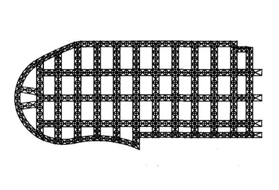
FIG. 1 Layout of steel roof truss
The steel structure installation of this project is divided into 5 parts, namely: steel structure column hoisting, plane main truss hoisting, middle longitudinal truss, tie rod, tie rod installation, catwalk and roof purlin hoisting, and roof panel installation.
The roof adopts the form of a space steel pipe truss structure, the roof is 114.00m long, 51.38m wide, and the highest point is 19.35m. The main truss has a total of 12 rods, the longest span of the main truss is 53.30m, and the height of the truss is 4.04m. Each truss member is composed of round tubes with various cross-section specifications. The upper chord section is ф194 mm X 7 mm, the lower chord section is ф299 mmX8 mm, and the web section is Φ 68 mm X 4 mm, Φ 76 mm X5 mm, Φ89 mm X6 mm, Φ95 mm X6 mm, Φ 121 mm X6 mm, Φ133 mm X6 mm, Φ108 mmX6 mm, the material is Q345B. The section specification of the roof rigid horizontal rod is ф121 mm X6 mm, the diagonal bracing is 68 mm X4 mm, Φ76 mm X5 mm, and the material is Q235B. The Ma Dao steel beam is H300 mm X150 mm X8 mm X12 mm, and the material is Q235B. The main roof purlins are H200 mm X 100 mm X3 mm X 3 mm, and the secondary purlins are CC163 mm X3 mm X 20 mm X 70 mm, and the material is Q235B.
2 Preparations for steel structure installation
2.1 Hardening and drainage of temporary storage yard of steel structure and surrounding sites
The temporary storage yard of the components at the construction site is located at the position specified in the general layout plan, and wooden squares are laid on the ground to reduce the deformation of the steel components when they are stacked. When stacking components, pay attention to the drainage direction, and do not obstruct the ground drainage.
2.2 On-site acceptance of steel components
The main purpose of the acceptance of steel components and materials is to count the number of components and deal with the components that may have defects on the ground so that components with quality problems do not enter the installation process.
2.3 Identification of steel structure members
In order to ensure the unification between the processing plant and the site, each component must be numbered accurately, the barcode on the nameplate of the component is scanned by the barcode scanning system, and the barcode data is read into the computer system for processing. Only when the steel structural members are stacked according to certain rules and sequences can they be installed in an orderly manner.
3 On-site assembly of steel structures
The height of the roof truss of the gymnasium is 4.04m, and the transportation and assembly scheme is adopted in the factory, which is manufactured in sections and assembled into hoisting units on site; The trusses that are hoisted in two parts shall be made and transported in two parts, and the trusses that are hoisted in two parts shall be made and transported in four parts, and the hoisting units shall be connected in one part.
3.1 Setting up the assembly site
In order to ensure the accuracy of the assembly of the components and prevent the assembly errors caused by the uneven settlement of the tire frame during the assembly process, the assembly site should be flat and compacted, and a 200 mm thick gravel cushion should be laid for compaction. Laying the steel subgrade box (Fig. 2)
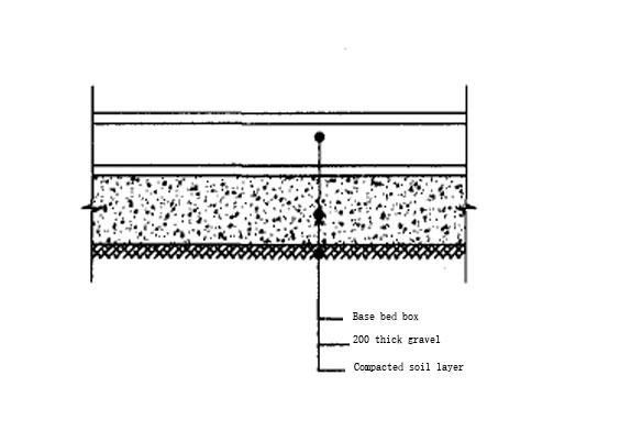
FIG. 2 Assembly site requirements
3.2 Design of assembled tire frame
Since the width and height of the section are beyond the scope of general transportation, so in the production of factory parts processing (including cutting, groove, docking and accessories processing and shot blasting, paint), the site of the whole assembly method. Considering that the shape of the assembled truss in this project is a plane truss, in order to make full use of the tire frame, and in combination with the construction period requirements, 4 groups of assembled tire frames are set up in the field.
3.3 The truss assembly process
Arrange and assemble the tire frame, put the ground sample and review it by a special person → the first section of the upper and lower chords is in place → the second section of the upper and lower chords is in place → the straight belly bar is assembled in place → the tire frame on the oblique belly bar in the position → start welding after confirming that it is correct.
4 Steel structure hoisting
4.1 Installation of finished supports
The concrete column top of the gymnasium is designed as a finished support. Before the support is installed, the connection between the upper cover and the lower base must be installed. After the support is installed in place, remove the temporary connector so that the support can rotate freely. The elevation of each axis column of the gymnasium is different, the middle concrete column is the highest, and the two ends are the lowest. Before the support is installed, measure the actual elevation of each column top plate, and measure the axis position of the steel support, and accurately draw the “ten” positioning line on the column top plate. After the support is hoisted in place, use the instrument to measure the installation position of the support, fine-tune it to the design coordinate position, and ensure that the center line of the support coincides with the installation lines of the upper and lower structures. The steel support connecting plate and the embedded plate should be parallel, and the absolute error of elevation should be less than 3mm. The installation error must be strictly controlled, otherwise there will be unpredictable huge and large installation stress.
In order to eliminate the influence of temperature stress on the truss, after the support is installed, it is not completely welded with the embedded plate, and then the final welding is carried out after all the structures are installed.
4.2 Main truss hoisting process
The 150 t crawler crane (according to the analysis to meet the hoisting requirements) travels on the crane walking road laid on the periphery of the site to the vicinity of the tower crane in the south, lifts the assembled main truss, and slowly lifts it to a height of about 30m. After the crawler crane stops stably, adjust the angle of the boom and jib to move the main truss above the installation point, lower it slowly, and place the main truss in place. During this process, workers are arranged separately to adjust the angle of the main truss and keep it stable through the ropes tied to both ends of the main truss, so that the main truss is vertically and slowly in place.
After the first truss is in place, reinforcement measures such as support rods and cable wind ropes should be set up immediately. After it is completely fixed, the support should be welded and fixed. After all the above processes are completed, the crane can release the hook. Next, the crawler crane returns to the vicinity of the assembly site and continues to hoist the remaining main trusses according to the above steps. During the hoisting process of the remaining main trusses, the main trusses in place were connected and fixed with support rods and tie rods, and the support rods and tie rods were hoisted in the field by 50t trucks. Repeat the above installation process continues until all the main trusses are hoisted.
4.3 Selection of wire rope
The lifting adopts 4-point binding, the outermost two wire ropes exert the main force, the distance between the lifting points is greater than 20m, the middle two wire ropes assist the force, and the 12 T hoist is used to properly tighten the truss to maintain stability.


