1、Project Overview
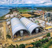
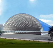
The construction area of the flat roof steel space frame structure of an eastern coastal coal power plant is over 100,000 square meters, which is the first time for domestic coal-fired units to construct such a large-scale steel space frame construction and renovation project, and there is little similar construction experience to draw on. Therefore, it is of great importance to plan the installation of the roof space frame reasonably and choose a construction plan that is safe, efficient and economical and does not affect the normal operation of the coal yard.
2、Design ideas, general scheme, technical architecture, technical principles, scheme and key technologies
Overall scheme: The coal yard closure project of an eastern coastal coal power plant adopts a large-span flat-plate space frame structure, which must meet the daily operation and work of the coal yard and ensure the coal storage requirements of the coal yard during the construction process; it must ensure smooth construction and not affect the coal transmission operation. Through comprehensive comparison of several schemes and argumentation and combined with the successful experience of similar projects in the past, the construction method of “bulk loading at height + cumulative sliding” was adopted to implement the steel space frame installation, taking into account the structural characteristics of this project. The overall implementation sequence is as follows: installation of the tire frame platform – sliding of the mesh frame assembly – platform dismantling.
3、Technical characteristics
3.1、Tire frame system
At the expansion end of the coal yard, a tire frame construction platform was erected. The tire frame construction platform adopts bolted ball node steel mesh frame. Each platform is 110m in length, 16m in width and 29.8m in height from the ground level, with three platforms arranged in three coal yards. Each platform is supported by 4 groups (2 per group) of lattice columns with a space frame size of 4×4m and a longitudinal spacing of 16m and 22m, and the top construction platform is a flat-plate space frame structure consisting of 4×4×4m bolted ball space frame with a platform thickness of 4m. After the platform is installed, a 1.2 m high safety fence is set up on three sides in the non-slip direction, and the safety fence is built with scaffolding steel pipes and covered with dense mesh. H-beam or C-beam is laid on the platform surface as keel, then covered with safety space , and then formwork or springboard is laid. A “zigzag” channel was set up on the east side of the platform and enclosed with dense mesh space ting to facilitate the personnel to go up and down.
3.1.1、Tire frame assembling
The structure of the construction platform is similar to the portal frame system composed of columns, beams, inter-column supports, etc. The whole platform can be regarded as a steel structure platform system. The three tire frame platforms are the same, and one of them is taken for elaboration.
(1) Lifting machinery selection: The tire frame columns are made of standard assembly section of pipe truss, each standard saves 750kg, and the weight of the whole column is about 5.3 tons. In order to ensure safety, the column is put down on the ground and assembled, the total height of the column is 26m, and the lifting height is about 26m. To ensure the lifting capacity of the crane, the crane stands as close as possible to the foundation of the column, and when the crane lifts the column, the working range is controlled within 15m as far as possible, considering the mechanical performance loss and consulting the performance table of the crane, it is proposed to use 80t auto crane, and the actual lifting height of the tire frame column is 26m. The actual lifting height of the tire frame column is 26m, and the lifting capacity is 9.0 tons > 5.3 tons when the elected main boom is 44m and the working radius is 15m. The crane meets the lifting requirements.
(2) Platform installation: Firstly, the platform space frame support columns were installed, which could be assembled on the ground as a whole and then lifted into position by a car crane. Use the longitude and latitude meter to control the verticality of the column, and then the column legs and pre-built bracket welding fixed, welding attention to the two welders symmetrical welding, welding technology to meet the design requirements; in place to complete the installation of cable wind rope [ cable wind rope and the ground angle of 45 degrees, using (0.6m * 0.6m * 0.5m) anchor ingot fixed, anchor ingot buried in the soil 1m, cable wind rope diameter 12mm.
(3) Construction safety measures for tire frame column and tire frame platform connection. The tire frame platform column is a pipe truss structure, and the tire frame platform is a bolted ball space frame structure, and the connection between the top and bottom is flange type connection. After the tire frame column is erected, cable wind rope is pulled around the column to ensure the three-dimensional stability of the column. The rods of the space frame platform on the top part of the column were pre-assembled on the ground, and the size of the pre-assembled unit was about 4m*16m, weighing about 2.6 tons. After lifting the pre-assembled platform to the top of the column by crane, the workers went up to install and fix the platform support on the top of the pipe truss column. The workers are sent to the top platform of the column by curved arm lift, and the safety belt is hung on the cross beam of the column. In order to prevent workers from losing their footing, fall arresters can be hung on the top of the column, and workers’ safety belts are tied on the fall arresters for twofold safety protection.
3.1.2、Tire frame dismantling (dismantling after completion)
After the overall skidding of the space frame is completed, the platform removal can be carried out in the reverse order of installation, and the order of removal, from high to low, from inside to outside. In the reverse order of installation, the upper part of the platform is preferred to be removed, and then the lower part of the platform is removed. The lower chord load calculation was increased for the 35-37 axes space frame part to ensure that the tire frame could be temporarily fixed at the lower chord node of the space frame by hanging a hand chain hoist to facilitate the removal of the tire frame platform, and the removed rods were transported to the ground by winch. Tire frame platform dismantling before pulling the column cable wind rope, pulling requirements and installation before the same; column removal with the same installation, the use of car crane lifting the whole demolition. The winch is 1t to meet the bulk demolition; the hand chain hoist is 3T, and 4-6 tools are arranged in each area (the maximum area weight is not more than 4t).
3.2、Space frame assembly and sliding system
The steel space frame assembly takes the fixed end space frame (16m*339m) as the first starting assembly unit, which is assembled on the tire frame platform; the crane is arranged on both sides of the installed platform for lifting, and after the assembly of the starting unit is completed, the skidding equipment arranged on each axis is used for skidding, skidding in the direction of 1 axis, skidding 8m each time, and then the crane is used on the east side of the platform to continue the auxiliary installation, and skidding is carried out after 8m is installed each time. Sliding will be carried out until the assembled module (96m*339m) of the first area is completed, then the whole area will be slid into position in Area 1 and then unloaded. The other two areas were constructed in the same way. Finally, the 37-39 axis area will be installed and closed by loose assembly.
3.2.1、 Sliding track arrangement
The sliding track is set on the sliding beam, fixed by the pressure plate, and the pressure plate is welded with the embedded parts. 43kg steel rails are selected for the track, and four sliding tracks are set, which are arranged along the A-axis, B-axis, C-axis and D-axis from the expansion end to the fixed end, and each sliding track is about 285m long. A 16m wide and 339m long assembly area was set up at the extension end.
(1) Placement, line check and foundation check. The position and size of the platform support points should be rechecked, and the installation can be started only after the axial position and elevation size meet the design requirements by the recheck check. b. The position, number and height of the temporary support points should be arranged uniformly, and the lower part of the support points should be properly reinforced to prevent the local force of the space frame support points from being too large.
(2) Lifting machinery selection: the maximum lifting height of the space frame component lifting is about 39m, taking bulk lifting, the mass of small assembled unit does not exceed 350kg, lifting range is about 10-18m; combined with the crane performance table, comprehensive consideration of the selection of 50t car crane, the selection state is 40.2m+15m.




 About Us
 2023-08-31


