


 About Us
 2022-10-26
1 Project Overview
The competition hall is a circular dome steel structure with a diameter of 116m and a height of 33.3m. The overall steel structure is a central pressure ring with a diameter of about 7.5m at the top of the steel structure above the civil structure with an elevation of 5.5m. The roof structure is composed of 24 trusses, 5 trusses and 1 steel ring beam The ring truss 5 of the bridleway structure with a width of 1m is set at the radius of 18.1m and 31.47m respectively, that is, the outermost truss of the structure has an inverted triangle section and the elevation is the lower chord connected with the V-shaped column of the civil structure above 11.69m. There are 24 groups in total. The outer truss of the upper chord is connected with the herringbone column of the civil structure above 5.5m. A total of 48 groups of steel structure facades and axonometric drawings of the competition hall dome are shown in Figure 1
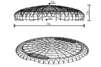
FIG. 1 Steel structure elevation and axonometric diagram of the dome hall
2. Construction difficulties and innovations:
In the southwest corner of the site, the running route of the crane outside the mountain shield is not conducive to the lifting of the competition hall in addition, and the construction period is tight. In combination with the characteristics of the dome structure, the construction method of bidirectional rotating cumulative sliding is adopted. Bidirectional sliding means that the roof structure of the competition hall is divided into two parts, and the construction is carried out in symmetrical rotation at the same time. The aerial assembly platform is set up from axis 2-3 to axis 2-11 (as shown in Figure 2). The location of aerial operation is more concentrated, the safety guarantee facilities are better, and the cross operation is relatively less, which can improve the construction safety factor. 2 SCX2800 280T crawler cranes are used as the main hoisting machinery for the upper altitude assembly of the sliding unit. In order to speed up the construction progress, another SC500-2 50T crawler crane is invested to assist in the hoisting of oblique supports, purlins, and other structural components of the upper altitude sliding unit.
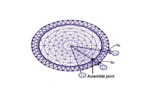
FIG. 2 Building a high-altitude assembly platform
3. Dome Roof Construction process and operation points
3.1 Construction process: division of sliding units → assembling of sliding units → building of sliding aerial assembling platform → setting of sliding track → design of slide way and support → design of hydraulic sliding device → formulation of sliding construction process → simulation analysis of sliding construction → synchronous control of hydraulic system → sliding dome closing.
3.2 Operation points
(1) Division of slip units. According to the site conditions, every 5 axis members are divided into one slide unit. For example, axis 2-3~2-7 are slide units 1-1. Axes 2-9~2-13 are slip elements 2-1. Axes 2-7~2-9 are assembly joints, and the closing joints of slip units are located between axes 2-29~2-31. Axis 2-7 and 2-31 are taken as the central lines, and the left half is zone A, with A total of 6 assembly units, while the right half is zone B, with A total of 5 assembly units. See Figure 3.
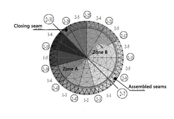
FIG. 3 Schematic diagram of slip unit division
(2)Each slip element consists of 3 trusses of radial truss and 5 trusses of the annular truss. The assembling sequence of sliding elements adopts the principle of “radial first, the circumferential second”, and combines the segmental way of truss for assembling. In the assembling process, the assembling accuracy and deformation of slip elements should be guaranteed. The Assembly sequence diagram of the sliding unit is shown in FIG. 4.
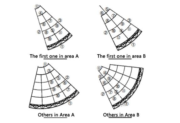 FIG. 4A, assembling sequence diagram of slip units in zone B
(3) Sliding track setting Sliding track is set below ring truss 1 (R1=18.0m) and 5 (R2=48.6m), there are two in total. A support frame is required for the inner slide, and a concrete column under ring truss 5 is used as a support frame for the outer slide. The support brackets are connected with lattice beams; The support columns of the outer sliding track are connected with H beams.
By reasonably determining the independent unit and closing position of bi-directional radial rotation cumulative slip, the assembled tire frame of the sliding unit, sliding track and slipper at different elevations, and hydraulic pushing device of the sliding unit are developed in this steel structure project, and the bi-directional rotation cumulative slip construction in the high altitude of the long-span dome steel structure is successfully realized.


