


 About Us
 2022-07-06
1 Project Overview
The shopping mall center consists of three building units: Supermarket in Area A, Shopping Center in Area B, and Shopping Center in Area C. Among them, the shopping center in Area B is about 260m long and has a total construction area of 220,000 square meters. The plane scale is large and complex.
Figure 1 Shopping center planning effect drawing
2 Main concrete structure
Due to the requirement of building appearance and functional layout, expansion joints are not allowed on the second floor of the shopping center, with a length of about 260m and a width of about 180m. In order to avoid cracks in the second-floor large chassis under temperature stress, according to the finite element stress analysis of the floor slab under temperature load, post-tensioned prestressed steel strands are set in the second-floor floor structure to apply pre-compression stress to the floor slab and other ultra-long Structural technical measures. Steel structure corridors and skylights between single towers above the second floor are supported by steel trusses or steel beams, one end is hinged connected to the main structure, and the other end is provided with bidirectional sliding bearings.
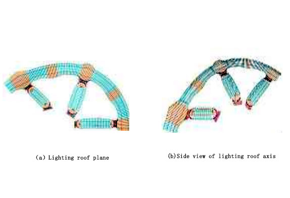
Figure 2 Rendering of the lighting roof of the shopping center
- Selection of steel structure for glass lighting roof
According to the architectural modeling requirements, the structural members of the atrium lighting roof between the single towers of the shopping center in Area B are arranged side by side in one direction, and the distance between the members is about 2.4m, so the glass can be directly used without secondary keel. In order to make the exposed daylighting roof steel structure achieve a simple and light visual effect, after repeated comparison and selection, the tension string beam structure was finally selected: the upper chord bending members and struts are made of round steel pipes, and the lower chords are made of round steel tie rods with their own tensioning devices. By applying to prestress to the lower chord cable, the upper chord flexural member generates counter-deflection, which greatly reduces the final deflection under the load, and improves the mechanical performance of the structure while making it lighter. When the chord beam structures are arranged side by side and have different spans, by setting the chord height in proportion to the span and optimizing the adjustment of the lower chord tension, the cross-sectional dimensions of the components can be basically consistent. At the intersection of the atrium, the steel structure of the daylighting roof has a large span and the single beam can not be placed directly on the main structure, and an ordinary steel pipe three-dimensional truss needs to be set up for conversion. The position of the steel pipe conversion truss is combined with the setting of the roof inspection channel to reduce the influence on the lighting effect.
There are more than 200 beams in the steel structure of the lighting roof in this project, and each of them has a different span and shape. For example, it is relatively simple to use the traditional flower basket bolt adjustment method and support removal method for tensioning construction, but the internal force of the cable is not easy to read and control; while the direct tensioning scheme through anchors and jacks is more difficult to construct, especially for each span. The shapes are different, and the complicated tension control standards are difficult to accurately control on the construction site.
After comparing and selecting various schemes, the intelligent steel tie rod that can freely adjust the tension and can measure and read its own tension is finally selected, which simplifies the process and quality control of the cable tensioning construction. The working principle of the intelligent steel tie rod system is to place a high-precision sensor on the intelligent connection sleeve of the steel tie rod component and achieve the performance of measuring the tensile force through five-point calibration. When the steel tie rod is prestressed, connect the signal acquisition device and the smart connection sleeve with a data cable, and the sensor in the smart connection sleeve will strain and transmit the strain signal to the display instrument or signal acquisition device through the data cable. The signal acquisition device can release the wireless signal, convert the signal into a tensile force value and display it on the software interface through the built-in force measurement software of the signal receiving devices such as laptop computers or mobile phones.


