


 About Us
 2022-02-18
The roof of a workshop adopts the form of the space frame structure, and the lower part is multi-point support of concrete column. To meet the workshop process production requirements, one side of the workshop is opened without a column. Figure 1 is the elevation of the workshop calculation model, and Figure 2 is the overall calculation model of workshop structure space. The short span of the workshop is 52 m, the long span is 56 m, and the column height is 12.0 m. The upper chord node of the network frame is supported on the steel column. To ensure the stiffness of part of the network frame on the opening side, the space frame is set on the opening side. The space frame adopts the forward quadrangle space frame, the space frame size is 4 m×4 m, the quadrangle height is 3.6 m, the nodes are welded balls, 13 space frames in the short span direction, 14 space frames in the long span direction. The roof adopts double slope drainage, a drainage slope of 1/10, and uses a welding ball upper small column structure to find the slope. Steel tubes 60×3.5, 76×4.0, 89× 4.0, 129×6.0, 159×8.0, and 180×10.0 are used for the upper chord, lower chord, and abdomen of the space frame. Q235B steel is used for the main structure. The theoretical steel quantity is 111.30T, and the steel quantity per square meter is about 38 kg.
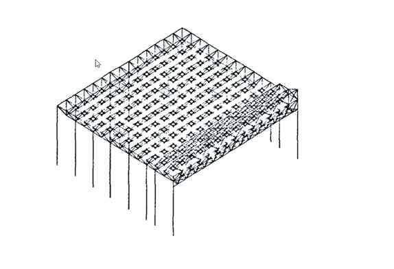
Figure 1 Overall calculation model of workshop structure space frame
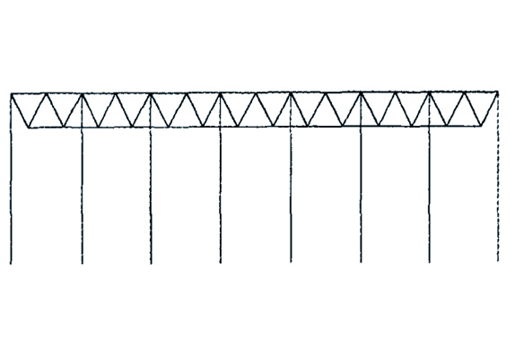
Figure 2 Elevation view of the overall calculation model of the workshop
2 Structure calculation
2.1 Load value
The dead load of the roof (roof sheet) is 0.5 kN/㎡; the live load of the roof is 0.5 kN/mZ; the wind load (basic wind pressure) is O. 35 kN/㎡; the ground roughness is Class B; the snow load is 0.35 kN/㎡; the seismic fortification intensity is 8 degrees; kind.
2.2 Load combinations
The safety level of the building is Class II, the importance coefficient is 1.0, the sub-item coefficient and combination coefficient are selected according to the “Code for Loads of Building Structures” (GB 50009-2001), 1.20 dead load + 1.40 live load, 1.20 dead load + 1.40 Wind load, 1.20 dead load+1.40×0.90 live load+1.40×0.90 wind load, 1.20 dead load+1.40×0.50 live load+1.30 earthquake load, l.35 dead load+1.40×0.70 live load+1.40×0 .60 wind load, 1.35 dead load + 1.40 x 0.70 live load, 1.35 dead load + 1.40 x 0.60 wind load.
2.3 Calculation results The 3D3S software compiled by Tongji University is used to space frame design and calculate the structure of this project. 2.3.1 Calculation of dynamic characteristics of the structure The results of the natural vibration periods of the first nine modes of the structure are shown in Table 1 on the next page. It can be seen from the mode shape diagram and the periodic table of natural vibration of the structure that the horizontal stiffness of the grid is large, the vertical relative stiffness is small, the stiffness of the substructure is also small, and the overall mode shape of the structure is relatively reasonable.
Table 1 Structure natural vibration period
| Vibration | ANSYS Calculated Values |
| Vertical bending mode shape of space frame |
1.2793 |
| X-direction translation vibration |
1.0938 |
| y-direction translation mode | 0.7419 |
| Overall torsional mode shape | 0.54162 |
| Space frame bending mode shape | 0.42156 |
| Side Truss Local Mode Shapes | 0.37356 |
| Space frame mode shape | 0.26875 |
| Space frame mode shape | 0.26703 |
| Space frame mode shape | 0.23535 |
2.3.2 Static calculation of the structure
The structural static calculation in this paper only considers the calculation of a combination of 1.2 dead loads + 1.4 × 0.7 live loads + 1.4 × 0.6 wind load. The calculation results of the maximum displacement of the structure are shown in Table 2, and the calculation results of the maximum internal force of the structure are shown in Table 3. It can be seen from Table 2 and Table 3 that the deformation of the workshop and the strength of each member of the grid frame meet the requirements, and the stress of the members at the mid-span and side trusses and supports of the grid frame is relatively large, which is also consistent with the stress characteristics of this structure.
Table 2 Maximum displacement of the structure
mm
| ANSYS Calculated Values |
Remark |
|
| Maximum X displacement | 38 | The maximum lateral displacement of the structure satisfies h/300 |
| Maximum y-displacement | 24 | The maximum lateral displacement of the structure satisfies h/300 |
| Maximum Z displacement | 108 | The maximum deflection of the structure meets L/250 |
Table 3 The maximum internal force of the structure
mm
| ANSYS Calculated Values |
Remark |
|
| Upper chord |
163.4 |
Middle position of space frame pan ventral |
| Ventral rod | 178.5 | Midspan position of side truss |
| Lower chord | 165.5 | Side truss and support position |
3 conclusion
Through 3D3S space frame design calculation shows that the strength, stability, and slenderness ratio of each component of the space frame workshop meet the requirements of the code, the structure is stable and reliable, meets the requirements of space frame design, construction, and use.


