


 About Us
 2022-08-05
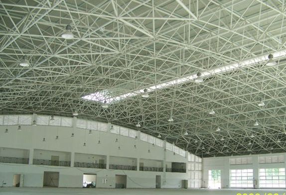
1 Warehouse Building Structural layout
Large steel structure warehouse building structure arrangement, mainly consider the arrangement of the frame and the vertical support system arrangement, and to form a stable structure system, choosing the reasonable support form and arrangement, can be on the premise of safe and reliable guarantee steel structure factory building use function, extend the service life of it, given that technical personnel on the deliberate choice.
1.1 Support system design
Supporting system of steel structure warehouse is an important part of the whole structure design, its main function is to connect support each plane frame, formed into a stable whole structure system, at the same time for the structure and component of out-of-plane stability provide relatively stable support, guarantee the stability of the whole steel structure system. At the same time, the support system also bears the role of transferring wind load, seismic force, temperature stress, and the longitudinal load of a 100T crane. In consideration of the design needs of the steel structure workshop, in the ridge, the top of the column, the upper and lower crane beam outside the column is provided with a long rigid tie rod, as well as between the columns supported by the column and the roof of the rigid tie rod. In the support layout adopted a balanced layout method, that is, along the longitudinal roof cornice position of the workshop set two horizontal support, in the transverse set four column support and roof support, forming four vertical and two horizontal support systems. Through the rigid frame, tie rod, support to form an overall stable structure system.
1.2 Support form selection
The main purpose of the support is to ensure the longitudinal rigidity of the factory building and to make the factory building form a stable structural system to bear the longitudinal crane load and wind load that transmits the factory building. The inter-column supports are arranged in three layers; the inter-column supports on the lower two layers bear a large load, and the materials are made of double-piece channel steel ladder type and arranged in a cross. The support material between the upper columns is made of single-angle steel, which is arranged in a cross; in order to reduce the temperature stress of the longitudinal members, there is no lower column support at both ends of the temperature section. The roof support is made of single-angle steel and arranged in a cross. The roof support and the inter-column support are arranged in the same column, and the support is reliably welded to the steel beam and column through the connecting plate.
1.3 Corner brace design
“The above roof and inter-column support systems are all arranged from the perspective of transmitting force and ensuring the overall stability and longitudinal rigidity of the plant skeleton. Therefore, the distance between the support points is large, and it is uneconomical to design the out-of-plane stability of the roof beams according to this. In the design of light steel structure, considering the skin effect of the panel, it is a relatively economical method to use purlins and corner braces to reduce the out-of-plane calculation length of the roof beam.” Considering the needs of the structural design of this project, it is necessary to ensure that the roof beam is out-of-plane stability, reduce the calculated out-of-plane length, prevent the buckling and instability of the compression flange (beam lower flange), and increase the stability of the compression flange. For the arrangement, one pair is set for each purlin in the compression area, and a pair is set for every other purlin in other positions.
1.4 Rigid frame design
Considering the structural characteristics of the large-scale steel structure workshop, the performance of the steel, and the economy, the rigid frame bears a large load, and the beam and column members are basically controlled by the strength, and the steel should be selected with high strength Q345-B. Combined with the preliminary calculation, the rigid frame beam adopts solid-web welded H-section steel. Considering the force, deformation and steel consumption, the beam end section is H (600~900) X200X6X10, the beam height is larger, and the web is thinner. The stiffening rib is -8@1500; the column design is combined with the LK value of the crane, so that the track is placed on one of the lower columns, and the upper column is designed with a solid belly H-shaped steel column, and the section height is about (1/12 ~ 1/7) H1 (H1 is the length of the upper column); the middle column and the lower column are lattice columns, all of which are solid-welded H-beam H400X250X10X16, and the transverse stiffener is -8@1500. Horizontal strip, the height of the column section is about (1/15~1/10) H2 (H2 is the length of the lower column), the upper, middle and lower columns are connected by a shoulder beam, and the shoulder beam doubles as the support of the crane beam (corbel) , the height of the shoulder beam is about (1/5 ~ 1/3) B (B is the height of the lower column), and the upper and lower plates of the shoulder beam are 20mm thick. The crane beam directly bears the dynamic load, and also adopts the solid-web welded H-beam. The column base is separated and connected to the foundation through anchor bolts.
2 Warehouse steel structural calculation
2.1 Load value.
Since this project adopts the form of a portal rigid frame, beams, columns and foundations all adopt steel connection technology. When calculating the internal force of the structure, in addition to fully considering the effects of constant, live, wind, and snow loads on the rigid frame, the effect of the dynamic load of the crane should also be fully considered. According to the requirements of the load specification, the standard values for calculation data are: Q1 roof dead load: 0.25 kN/m2; Q2 roof live load: 0.5 kN/m2; basic wind pressure: 0.35 kN/m2; Q3 basic snow pressure: 0.6 kN/m2. Q 4 Crane load: Q=100T, maximum wheel pressure 41t, minimum wheel pressure 10.5t; 50T crane maximum wheel pressure 40.3t, minimum wheel pressure 8.8t.
2.2 Internal force calculation.
The structural internal force of this project is calculated by PKPM series software STS steel structure calculation software. The calculation results show that the maximum stress ratio of the steel beam of the steel structure workshop project is 0.94, the absolute deflection (constant + active) of the steel beam is 1/411, and the maximum stress ratio of the lattice steel column single branch is 0.86. The stress of the strip is relatively small, and it is basically controlled according to the slenderness ratio of the compression member of 150. The maximum displacement of the top of the column under the horizontal action of the crane (braking force) is 1/450. The design indicators of this project meet the “Code for Design of Steel Structures”. (GB50017-2003) requirements. The workshop and crane fully meet the requirements of the manufacturer.
3 Treatment of longitudinal expansion joints
Although the longitudinal 270m of the steel structure warehouse meets the requirements of the relevant specifications, in the design process, considering the large span and partial load of the steel structure workshop, the designer within 97.5m was mainly based on the “Code for Design of Steel Structures” (GB50017-2003) The selection and control of various relevant parameters, and the structure outside this range is controlled in accordance with the “Technical Specification for Steel Structure of Portal Rigid Frame Lightweight Buildings” (CECS 102: 2002) to reduce the amount of steel used. According to this idea, setting a seam at 97.5 meters and separating the two parts not only reduces the difficulty of engineering design but also reduces the cost so that the difficulty is only in the design of the rigid frame of the double-decker crane.


